|
|
Testing Attenuation In A Fiber Optic Communications Link 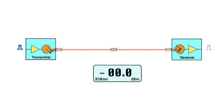 In a fiber optic link, light from a transmitter is coupled into a fiber in the cable plant and transmitted to a receiver on the other end of the link. As the light travels down the fiber, its optical power is attenuated by the losses in the fiber (scattering and absorption) and losses at connectors or splices. To test the loss of a signal in a fiber optic link in a way that mimics the way the link transmits data, we use an insertion loss test. We use a test source that is similar to the source in the transmitter and a calibrated power meter to simulate the receiver. Launch and receive reference cables are used to connect our source and meter to the cable plant - think of them as the patchcords you use to connect equipment. Here is a diagram of how we make an insertion loss test. See how it simulates the actual fiber optic data link? 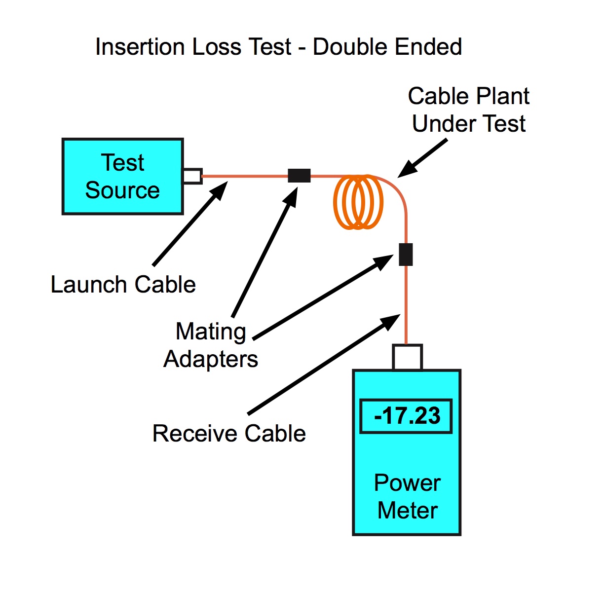 We need these test instruments and components
The loss is measured in dB - a relative measurement on the meter. Remember dBm is absolute optical power used for measuring the output of a transmitter source or input of a receiver, while dB is a difference between two measurements in dBm. So if the output of the transmitter source is SdBm and the input at the receiver is RdBm, the difference between the two: SdBm-RdBm = LossdB or the loss in the link. Since loss is a relative measurement, we need a reference point for the power of the test source to set a "0 dB" reference. For most tests, we use the output of the launch cable attached to the source. We simply:
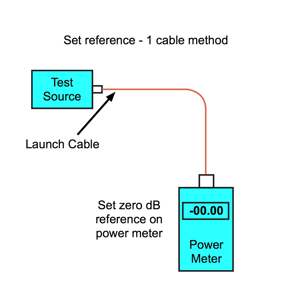 With most power meters, when measuring in the dB measurement range, we have a "0dB" set button. Push that button and we can set the meter to read "0 dB" at any power level, making it convenient because it will read loss directly - it's ready to measure loss. Once we set the 0dB reference with the launch cable, we can test our reference cables. If they aren't good, all our tests will be bad. Disconnect the launch cable from the meter - don't touch it at the source once you set the 0dB reference level as disconnecting/reconnecting it may change the power level.
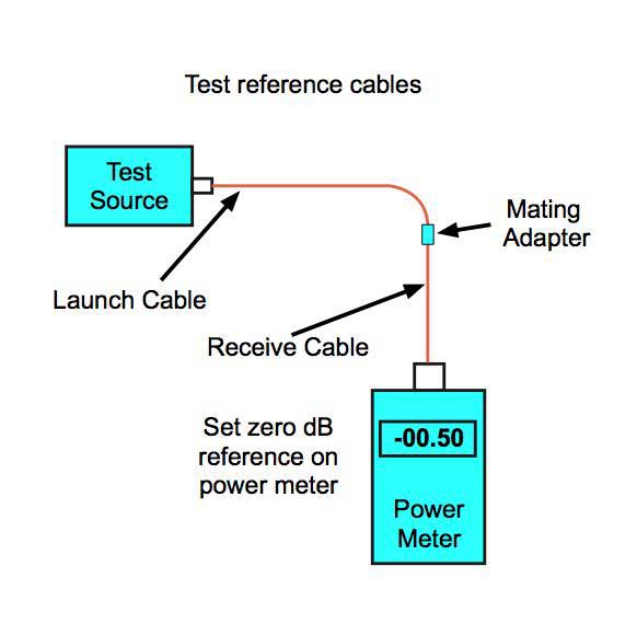 Here we are testing the reference cables and the connection loss is 0.5dB - that's not great but acceptable. Less loss here indicates the connectors are better and will give better test data. Don't touch those meter settings! Some people are tempted to reset the 0dB reference at this step, but that would lose our 0dB reference which is the output of the launch cable. )We'll talk about other ways to set the 0dB reference later.) This step just tests the reference cables. Now we're ready to test our cable we want to test. Here are the steps:
See if you can follow those steps in this animation - you will need to watch it several times to get all the steps of the sequence: 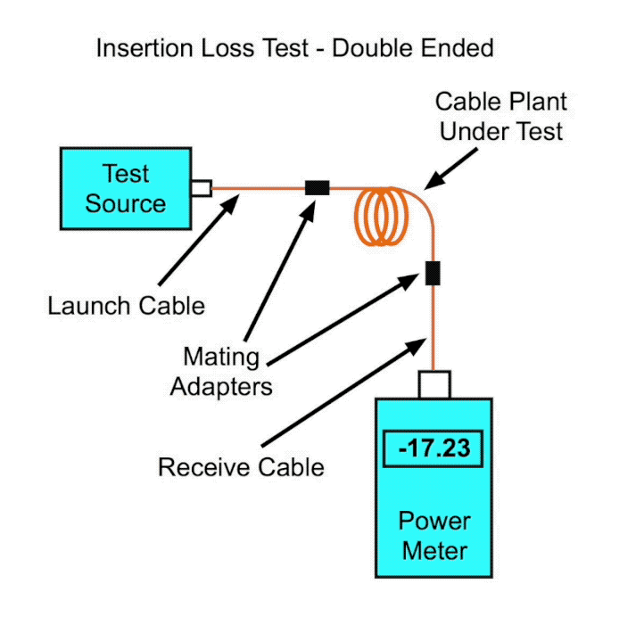
Review: To test insertion loss, we need;
And the procedure is:
|
Got that? OK let's start testing. |
|
|
|

|
|