Outside Plant Construction GuideIntroduction Review Of Fiber Optic Technology. Project Preparation And Guidelines. Underground Cable Construction. Underground Cable Installation. Aerial Cable Installation. Completing Outside Cable Plant Installation. Underground Cable InstallationCable Pre-installation Procedures The following items are key considerations in preparation for installing the fiber optic cable when the construction is ready for cable placement. Optical fiber cable should be carefully inspected when received and stored safely onside during storage before installation. All cables should be tested to ensure the cable was not damaged in shipment. All personnel handling cables, on reels, drums or spools (all three names are often used) or during installation, should be properly trained. Installation Guidelines Follow the cable manufacturer's recommendations as no one knows how to handle cable as well as the company which made it. Fiber optic cable is often custom-designed for the installation and the manufacturer may have specific instructions on its installation. Check the cable length to make sure the cable being pulled is long enough for the planned cable run. Try to complete the installation in one pull if possible. Prior to any installation, assess the route carefully to determine the methods of installation and obstacles likely to be encountered. Pre-installation Cable Inspection
Testing Fiber Optic Cable On The Reel All optical fiber cables must be tested while on the reel, prior to deployment. Installing cable is a time-consuming and expensive process so it is important to ensure the cable is good before installation. If there is any sign of damage to the reel of fiber, all fibers may need to be tested. If the cable and reel look undamaged, a sampling of one fiber per buffer tube or ribbon may be adequate. 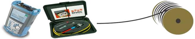 Pre-test the cable with a Visual Fault Locator (VFL) and/or an Optical Time-Domain Reflectometer (OTDR). The VFL will show if the fiber is continuous; the OTDR will confirm that the fiber still meets specifications and has no damage. A pigtail with a mechanical splice or a bare fiber adapter can be used to connect bare fibers to the VFL or OTDR. Testing shall be done on fibers in one direction at 1550nm, using a pulse width of 30ns since 1550nm is the wavelength that shows stress losses in the fiber best. OTDR traces must be stored and an electronic copy submitted to the project manager. Cable Handling Twisting Cable Do not twist the cable. Twisting the cable can stress the fibers. Tension on the cable and pulling ropes can cause twisting. Use a swivel pulling eye to connect the pull rope to the cable to prevent pulling tension causing twisting forces on the cable. 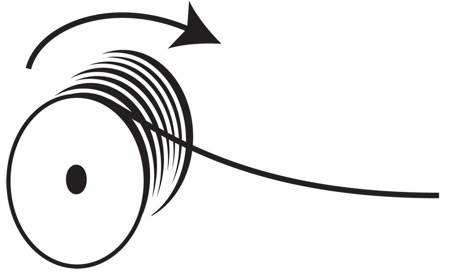 Roll the cable off the spool instead of spinning it off the spool end to prevent putting a twist in the cable for every turn on the spool. When laying cable out for a long pull, use a "figure-8" on the ground to prevent twisting. The figure 8 puts a half twist in on one side of the 8 and takes it out on the other, preventing twists. Cable pay-off - over the top or from the bottom? 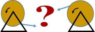 For most installers, over the top makes more sense. However, advocates of from the bottom when jetting / blowing cable do exist. Ultimately, faced with this choice, a contractor must determine which option is favored by the client. Installing Swivel Pulling Eyes: Cable manufacturers install special strength members, usually aramid yarn (Dupont Kevlar), for pulling. Fiber optic cable should only be pulled by these strength members unless the cable design allows pulling by the jacket. Any other method may put stress on the fibers and harm them. Swivel pulling eyes should be used to attach the pulling rope or tape to the cable to prevent cable twisting during the pull. 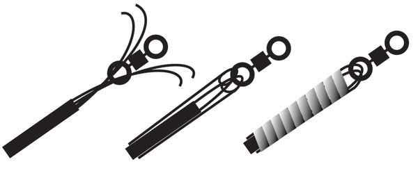
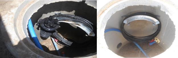
Cables should not be pulled by the jacket unless it is specifically approved by the cable manufacturers and an approved cable grip, often called a Kellems Grip, is used. These grips are usually tied to the strength members also. 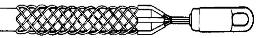 Pulling Rope Special fiber optic pulling tapes should be used if available. An 8mm polyester or polyaramid pull rope must to be used for optical fiber cables that are to be pulled in by hand. When using a hauling winch, a 12,5mm or thicker polyester or polyaramid rope should be used as hauling rope. Ropes manufactured from nylon are not suitable as their stretch factor is too high and they can potentially cut into ducts. Steel hauling rope or galvanised wire must never be used as they can damage ducts and/or cables. Duct Fill Ratios for Hauling 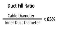 Fill ratios are calculated by comparing the area of an inner diameter cross-section of the inner-duct to the outer diameter cross-section area of the fiber optic cable. For optimum hauling performance, it is recommended that the cable-to-duct diameter fill ratio does not exceed 65%, or as per cable spec sheet. How To "Figure 8" Cable for Intermediate Pulls in OSP Installations On very long OSP runs, typically longer than approximately 2.5 miles or 4 kilometers, it may be necessary to use an automated fiber puller at intermediate point(s) for a continuous pull or pull from the middle out to both ends (midspan pull.) When laying loops of fiber on a surface during a pull, use figure-8 loops to prevent twisting the cable. The figure 8 puts a half twist in on one side of the 8 and takes it out on the other, preventing twists. 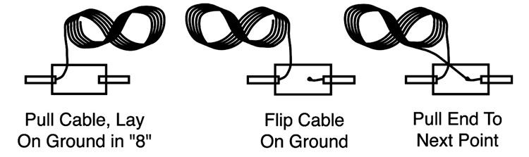 Bend Radius Do not exceed the cable bend radius. Fiber optic cable can be broken when kinked or bent too tightly, especially during pulling. If no specific recommendations are available from the cable manufacturer, the cable should not be pulled over a bend radius smaller than twenty (20) times the cable diameter. 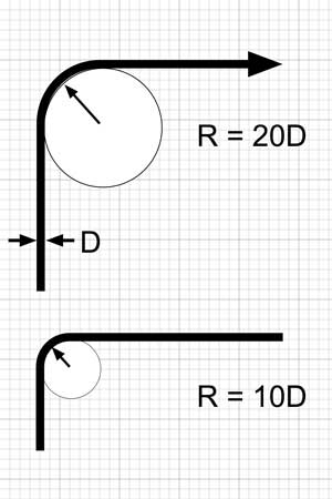 After completion of the pull, the cable should not have any bend radius smaller than ten (10) times the cable diameter. Pulling Tension Excess pulling tension on a fiber optic cable can damage the fibers. Tension limits assume the fiber is being pulled properly using the cable strength members. Fiber optic cable should only be pulled by the cable strength members unless the cable design allows pulling by a grip on the jacket. An approved cable grip, often called a Kellems Grip, must be used. These grips are usually tied to the strength members also. Any other method may put stress on the fibers and harm them. Do not exceed the maximum pulling tension rating. Consult the cable manufacturer and suppliers of conduit, innerduct, and cable lubricants for guidelines on tension ratings and lubricant use. When pulling long lengths of cable in conduit or innerduct (up to approximately 3 miles or 5 kilometers in the outside plant, use proper cable lubricants but make certain the lubricant is compatible with the cable jacket.  If possible, use an automated puller with tension control and/or a breakaway pulling eye. On very long OSP runs (farther than approximately 2.5 miles or 4 kilometers), midspan pulls are necessary. Pull from the middle out to both ends or use an automated fiber puller at intermediate point(s) for a continuous pull. When laying loops of fiber on a surface during a pull, use figure-8 loops to prevent twisting the cable. Cable Pulling Cables may be installed in ducts by pulling or blown in with special equipment. In this section we will cover both techniques, starting with cable pulling. Pre-Installation Check Prior to any hauling, the following must be confirmed: · Maximum allowable pulling tension for the cable being installed · Minimum allowable bending radius during installation for the cable · Minimum allowable bending radius after installation for the cable · Cable length required for each pull · Cable length required at the splicing locations Duct Rodding Rodding is used to clear the duct passage and install the pulling rope, using fiberglass pushrods. An alternative is to use air-blowing device.  · Push the rod into the duct until the front end of the rod reaches the adjacent HH / MH. · Attach the pulling rope to the end of the rod at the adjacent HH / MH. · Next, pull the rod and pulling rope back through the duct If the air pressure method is preferred, the pulling rope will be blown through the duct until it reaches the adjacent HH / MH. Duct Testing and Cleaning To clean the duct, attach a cylindrical brush or close-fitting mandrel and a second rope to one end of the installed pull rope and pull this through the duct. 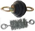 If the cable sample or mandrel cannot pass through the duct, consult with the Client on whether to switch to an alternative duct or to repair the designated duct. Midspan Pulls and Center Pulls Pulling long cable runs may be difficult or impossible due to the friction between the cable and the duct. Lubrication helps but often does not completely resolve this issue. Guides are available from lubricant manufacturers to estimate the lengths possible to pull with proper lubrication. To assist with alleviating this issue, specialized techniques, such as center pulls or midspan-pulls can be used with either the manual pull or winch methods. Midspan Pulls Midspan pulls are used to provide a series of shorter, lower-tension pulls in one direction. In a midspan pull, the cable is pulled through duct to a handhole or manhole and the pull is continued until sufficient cable has been pulled for the rest of the length of the pull. Cable that is pulled is laid in a figure 8 pattern on the ground 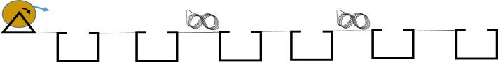 Center Pulls In a center pull, the cable is placed in the middle of the pull and pulled off the spool in one direction until the end of the pull is reached. Then the cable is continued to be rolled off the reel into figured 8s on the ground. Then the figured 8 cable is flipped over and the end is pulled in the other direction. Ensure the cable is long enough for the entire pull before beginning the operation. Communication, directed by a team leader with team members positioned at each HH / MH is essential, for that the pulling action to be achieved in a synchronized manner. Communication via the use of either cell phones or two-way radio is desirable. 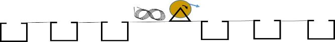
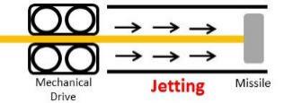
Pulling Tension The maximum allowable pulling tension on fiber cable can vary and is dependent on the cable construction. The maximum tension for a particular cable can be found on the cable spec sheet. Except for short runs or hand-pulls, tension must be monitored on the pull rope. The use of a breakaway swivel can be used to ensure that the maximum tension of the cable is not exceeded and should be used as a fail-safe rather than a primary means of monitoring tension. Cable lubricant is recommended for most fiber optic cable pulls as a means of lowering pulling tension. Pulling a new fiber optic cable over an existing one is never recommended due to the possibility of entanglement. Techniques exist to pull into ducts new ducts, especially the thin fiber ducts, that can allow safely adding cables to current conduits. Access Build (Drops) The final connection to a building, often called the drop, is unique. Drops are often fraught with deployment challenges including multiple tight bends and space constraints. The last phase of an installation is normally the most expensive and time consuming part of any overall fiber project. Careful planning and installation can mitigate the problems. Introduction to Air-Assisted Installations (Blowing or Jetting) Jetting or blowing (also sometimes referred to as floating) are two air-assisted cableinstallation techniques. Blowing cables does not really blow the cables in the duct, but consists of pushing the cable with a tractor mechanism while blowing compressed air into a preinstalled duct to float the cable in the duct and reduce friction. The air flow to helps float the cable inside the duct and reduces friction between the cable and the duct, making it possible to push the cable considerable distances in a duct. This technique provides an efficient, stress-free deployment in far greater distances than possible when pulling cable. Air-blown cable can be use in premises cabling installations as well as OSP. 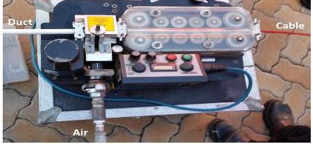 Jetting and blowing differ in how pulling force is applied to the cable. Jetting uses a missile at the front end of the cable. A differential pressure across the missile head creates a pulling force on the cable. Blowing does not use a missile - instead, the pulling force on the cable is due to fluid drag of air rushing along the cable - this pulling force is distributed along the cable length. A mechanical pushing device is common in both methods. 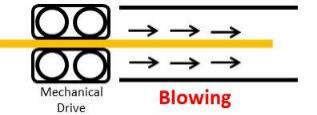
It is common wisdom that hydraulics can give you higher forces than pneumatics. Mindful of this, a blowing machine with a pneumatic drive is recommended for cables up to 15mm in diameter and a blowing machine with a hydraulic drive is recommended for cables with a diameter in the range from 14 - 32mm. The key parameters when installing fiber cable in ducts are blowing distance and time. 1000 to 2000m is a typical blowing length. Typical installation speeds are 40-50 meters per minute under an air pressure of 10 bars (atmospheres). Most routes can be blown with a 10 bar supply. Smaller diameter and lower weight cables make possible larger blowing distances, so blowing cable is perfect for the new generation of microcables. The maximum cable push force will decrease as the duct inside diameter increases, reducing the achievable blowing distances. Blowing distance is directly related to the weight of cable, the pressure used and, friction from the inside of the microduct. Cable can be successfully blown further than 2-km when blowing heads are used in tandem.  Additional air can also be inserted further down, to achieve more distance.  Preparing For Blowing Cable Survey the complete route prior to blowing in order to determine the location of HHs / MHs and distances between then. Determine where coupling of ducts are necessary. Survey the route for the accessibility of terrain for the use of the intermediate (mid-point) fiber blowing equipment. Identify specified ducts to be utilised. And as always, consider the accessibility of HHs / MHs to the splicing vehicles. Jetting / Blowing The Right Cable Choosing the right cable is extremely important for any installation. Strictly speaking, the purpose of the cable is to protect the fibers during installation and the service lifetime. Cables share some but not all characteristics and you need to ensure you install the cable type appropriate for the application. Micro cables are designed with high-density polyethylene (HDPE) outer sheaths to minimize friction with the inner surface of micro ducts. They are also designed with the necessary stiffness properties to resist buckling forces and to negotiate changes in direction. The cable on the drum must be covered until just prior to installation to protect the jacket from heat due to exposure to the sun and getting dirty. Air-Assisted Installation Practices 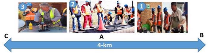 Consider a very long link installation. Cable reels are typically supplied containing 4-km of cable. Mindful of this, reels are placed midway of a 4-km length. Theres plenty of evidence suggesting that the most efficient cable installation would involve two 2-km jetting shots (A to B followed by A to C). After jetting A to B, a figure-8 will be created at the midway point, to gain access to the end point of the cable previously on the drum. Next, the figure-8 end will be jetted in the other direction. One ought to be able to install 4-km of cable in one placement of the cable drum and blowing equipment consisting of; 2-km of cable jetting in opposite directions with 2-km of "figure-eighting" in the center. Adding more air blowing to a microduct further down can also increase the achievable distance. If at some point the cable movement slows down during the blowing process, then instead of taking a 2-km run, the jetting could be reduced to only 1-km. This would call for a second figure-8 to be made at the 1-km mark. Duct Integrity Testing (DIT) All team members MUST wear eye protection during DIT testing as small particles can be blown out of ducts through the holes in the DIT catcher. Air Test
Foam Sponge Test - cleaning the duct:
Mandrill Test One can test ducts for bends, kinks or blockages that may hinder blowing cable by doing a mandrel test to see if one can blow a sample down the duct.
Pressure Test A pressure test checks for coupler leaks or microduct punctures that could affect blowing cable.
 If the duct fails DIT tests, consult with the relevant authority on whether to use an alternative duct or to repair of the designated duct. Micro Duct Fill Ratio For optimum jetting / blowing performance, ensure that your cable-to-duct diameter fill ratio does not exceed 76%. This is determined and provided by the microduct supplier. It is wise to always verify this by checking the provided spec sheet. Cable Blowing Lubricants Adding a small amount of lubricant to a tight-fitting foam carrier (sponge) before blowing it through the duct, will provide an open and lubricated pathway. It is argued to give better results compared to coating both the duct and cable with lubricant. Odd, huh? Let me try to explain. Lubricant on a cable jacket apparently makes it too "slippery" for optimal laminar-flow jetting.  Lets not forget that the air "pushes" on the jacket through friction. A too low friction jacket will not easily be pushed by air. Normally, as little as 0.25 litre of lubricant is required to coat 2km of cable. Suggested Air-Assisted Installation Practices
Management of Cable Slack When handling cable, always wear; a protective overall, gloves and safety boots. Never exceed the recommended cable bend radius:
 What is the minimum bend radius of your microducts? Formula:
Radius min =10 x OD
Therefore,
if you have microduct has a OD of 10mm, your Radius min
=100mm
Figure-8-ing The preferred size of a figure-8 is about 5m in length, with each loop about 2.5m in diameter. To start with, set up two traffic cones 5m apart then pay the cable off the top of the reel and loosely weave it around the cones in a figure-8 pattern - on top of a groundsheet. Large relaxed loops will help prevent the cable from becoming entangled. 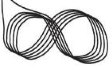 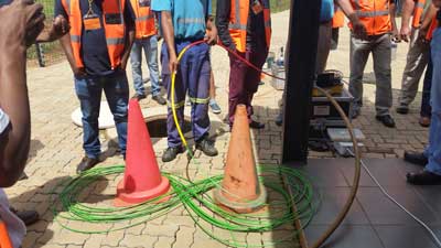 Continue to figure-8 the cable until the remainder of the reel is played off. In order to pull from the figure-8 - it is necessary to flip it over, a task that requires a minimum of three people -one at the centerand one at each end. The required cable end will now be at the top of the figure-8. Special Micro Duct Tools and Accessories Acceptable Cable Drum Jacks Must Be Used 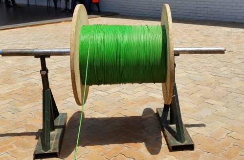 Tools Ensure that installers are fully educated on the proper use and operation of any tool before starting a job. 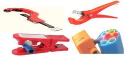 It is essential to always use the prescribed cutting tools to produce a clean and straight cut to a microduct, before inserting a coupler. Bullet Fixed to the end of the fiber cable before blowing starts, to guide the cable through the microduct. 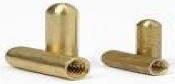 Sponge Used for removing dirt and/or moisture from a microduct.  Shuttle Used to check the microduct for bends, kinks or blockages.  Caps & Plugs Used for the permanent or temporarily sealing of unused microducts to prevent water and dust from getting into ducts. 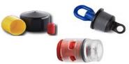 Use only the prescribed connectors and end-plugs. Couplers Used for the air-tight coupling of microducts. 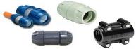 De-bur Tool Allows for one to round-off a microduct after cutting - before adding a coupler, to produce an air-tight connection. 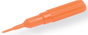 Locking Tool Used to firmly lock the microduct into a connector. 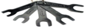 Cable Carriers Parachutes capture the air within a duct, tugging along with it the cable. In the absence of air pressure, they collapse allowing for easy pullback. An alternative is to use an Inflatable Carrier. 
Inflatable Carrier  (C) 2018 The Fiber Optic Association Inc. Return to the OSP Construction Guide Index |
|
|