The
Fiber Optic Association
- Tech Topics
Fiber Optic Lighting
Introduction
Optical
fiber can be used for transmitting light from a source to a remote
location for illumination as well as communications. In fact, fibers
are made to not only transmit light but to glow along the fiber itself,
so it resembles a neon light tube. Applications for fiber optic
lighting are many, generally based on utilizing the special attributes
of the fiber as well as its unique characteristics.
Typical Applications
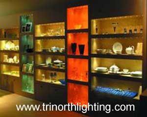
| Museum displays |
 |
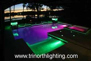
| Pools |
 |
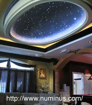
| Starfield Celings |
 |
Why Use Fiber Optics For Lighting?
Using
fiber for remote lighting has many advantages, some of which are more
important for special types of applications than others.
Heat-Free Lighting:
Since the light source is remote, the fiber transmits the light but
isolates the heat from the light source from the illumination point, an
important consideration for lighting delicate objects, such as in
museum displays, that could be damaged by heat or intense light.
Electrical Safety:
Underwater lighting such as used in swimming pools and fountains or
illumination in hazardous atmospheres can be done safely with fiber
optic lighting, since the fiber is nonconductive and the power for the
light source can be placed in a safe location. Even many lights are low
voltage.
Precise Spotlighting: Optical fiber can be combined
with lenses to provide carefully focused light on extremely small
spots, popular for museum exhibits and jewelry displays, or simply
light a specified area precisely.
Durability: Using optical
fiber for lighting makes for much more durable lighting. Optical fiber,
either plastic or glass, is both strong and flexible, much more durable
than fragile light bulbs.
The Look of Neon: Fiber
that emits light along its length, generally called edge-emitting
fiber, has the look of neon tubes for decorative lighting and signs.
Fiber is easier to fabricate, and, since it is made of plastic, is less
fragile. Since lighting is remote it can be placed at either or both
ends of the fiber and sources can be safer since they are low voltage
sources.
Vary the Color: By using colored filters with
white light sources, fiber optic lighting can have many different
colors and by automating the filters, vary colors in any preprogrammed
sequence.
Simpler Installation: Fiber optic lighting does not
require installing electrical cables to the light locator and then
installing bulky light fixtures with one or more bulbs on location.
Instead, a fiber is installed to the location and fixed in place,
perhaps with a small focusing lens fixture, a much simpler process.
Often several fibers can use a single light source, simplifying
installation even more.
Easy Maintenance: Lighting in hard
to access areas like high ceilings or small spaces can make changing
light sources difficult. With fiber, the source can be in an easily
accessible location and the fiber in any remote place. Changing the
source is no longer a problem.
How Fiber Optic Lighting Works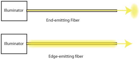
Fiber
optic lighting uses optical fiber as a “light pipe,” transmitting light
from a source through the fiber to a remote location. The light may be
emitted from the end of the fiber creating a small spotlight effect
(also called “end glow”) or emitted from the outside of the fiber along
its length, looking like a neon or fluorescent tube (also called “side
glow”).
The light source is usually called a “fiber optic
illuminator” and consists of a bright light source and often some
optics to efficiently focus light into the fiber. Sources must be
bright, so quartz halogen or xenon metal halide lights are commonly
used. Smaller fibers may also use LEDs which very efficiently couple
light into fibers but do not achieve the light levels of the other
lamps.
Optical fibers used for lighting are similar to fibers used
in communications, but optimized for transmitting light not high speed
signals. The fibers consist of a core that transmits the light and an
optical cladding that traps the light in the core of the fiber. Unlike
communications fibers that use small cores to maximize bandwidth,
lighting fibers use large cores with thin claddings to maximize
coupling of the light from the illuminator into the fiber.
Side-emitting fibers have a rough interface between the core and the
cladding to scatter some of the light out of the core along the length
of the fiber to create a consistent lighted look similar to neon light
tubes.
Lighting fibers can be made of glass, just like
communications fibers, or plastic. If the fibers are glass, they are
usually very small diameter and many are bundled together in one
jacketed cable to provide enough light transmission. Larger diameter
plastic fibers are also used, perhaps more commonly, because they
are inexpensive and easier to install, but they have higher light loss
and cannot withstand as hot a temperature, sometimes limiting the light
input from a source.
Types of fiber
End-emitting Fiber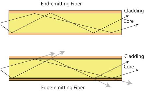
End-emitting
fiber is generally a step-index multimode fiber with a large
transparent core that transmits the light and thin transparent cladding
that traps the light in the core in an optical process called “total
internal reflection.” The core is large in comparison to the thin
cladding as that makes it more efficient in coupling light from the
illuminator. The cladding does not transmit light, so any light coupled
into the cladding will not be transmitted by the fiber.
End-emitting
fibers are generally made from plastic as it can be made in larger
sizes than glass and is less expensive and easier to install. Plastic
optical fiber (POF) is made in sizes from 0.1 to 20 mm in diameter.
Glass fibers are generally made in much smaller sizes (hair thin, about
50-150 microns or 0.05 to 0.15 mm) and bundled together to make larger
diameter cables.
The choice of core and cladding materials
determines the angle of light rays accepted from sources and
transmitted by the fiber (called modes), defined by a specification
called numerical aperture(NA). The light will exit the fiber in a cone
that shows the size of the NA with larger NA having a wider output
cone of illumination. Higher NA fibers also couple light from sources
more efficiently, as it will capture light at higher angles emitted by
the source. Typical fibers have acceptance cones of 30-60 degrees,
corresponding to NAs of 0.3-0.6. When optics are used to focus the
light emitted from the fiber, the NA of the fiber must be known to
choose appropriate optics.
End-emitting fibers transmit
light well. Glass fibers are more efficient at transmission because
glass is more transparent than plastic, but because of the
inefficiencies of packing fibers into bundles, spaces between the
fibers in the bundles means much of the illuminator light is not
coupled into fiber cores. However, glass fibers may be more tolerant to
heat generated by the illuminator, allowing greater illuminator
intensity and providing more light from the end of the fiber.
Edge-emitting Fiber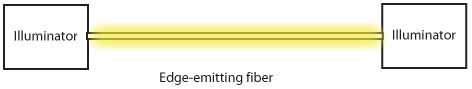
Edge-emitting
fiber is basically similar to end-emitting fiber except the
core/cladding boundary is designed to be slightly inefficient. Instead
of trapping all the light in the core, the boundary is rough and some
light is scattered into the cladding where it becomes visible. By
careful design, the fiber can have a smooth glow that looks much like a
neon light tube. Smaller edge-emitting fibers have been woven into
tapes that emit light in a band.
Since much of the light is lost by
the edge-emission along the fiber, edge-emitting fiber has high
attenuation. This may limit the lengths of edge-emitting fiber that can
be used. This can be alleviated by illuminating the fiber from both
ends by using two illuminators or looping the fiber back around to the
same illuminator, or using reflective end caps to send excess light
back up the fiber from the far end.
Illuminators , Types of Sources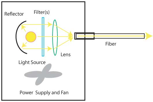
The
illuminator contains the light source for the fiber as well as optics
and filters designed to produce the amount and type of illumination
desired. While the amount of light coupled into the fiber is the
primary consideration in choosing an illuminator, many other factors
are involved, which has driven the market to offer many types of
sources.
The power coupled into the fiber or fibers, as many sources
will accommodate more than one fiber, will generally determine the type
of light source used. Quartz halogen lamps are used in many
illuminators. These sources, developed as spotlights or lamps for
projectors, come in both low and AC voltage versions, with a wide range
of power outputs. Quartz halogen lamps are usually made integral with
reflectors that make focusing light into a fiber simpler. New Xenon
metal halide lamps that have high power output but require high voltage
power have been introduced that offer greater efficiency.
Lower
power systems have been able to use LEDs which have higher efficiency
but limited power. New LEDs are becoming brighter and even more
efficient, making LEDs a viable source for more systems.
Illuminators
include more than just lamps or LEDs. Lamps may need reflectors if they
are not built into the lamp, as well as lenses to focus light into the
fiber. High power sources may have infrared (IR) filters to
reduce heating of the fiber and ultraviolet (UV) filters to prevent
damaging the fibers during long-term exposure.
Power sources for the
lamps or LEDs will be needed, including dimming capability if desired.
Since most lamps generate lots of heat, fan-forced ventilation will be
designed into many illuminators.
Lamps are easily filtered to
provide colored light in the fiber. Using moveable filters, usually in
a wheel powered by a small electrical motor, allows the color of the
light to be changed in a chosen sequence.
The complexity of
illuminators precludes most users making their own, but numerous
manufacturers offer various models optimized for various fiber types
and applications. Working with these manufacturers is the best way to
choose an appropriate illuminator and compatible fibers.
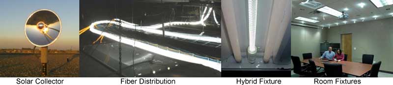
Passive
lighting using fiber optics is being done using roof-mounted solar
collectors that deliver sunlight over fiber to rooms in a building or
below decks for ships.
End-Emitter Fixtures
Normally,
light exits an end-emitter fiber in a cone of light defined by the
numerical aperture of the fiber. In some cases, that will be adequate
for illumination. However, it is sometimes desirable to focus the light
on a smaller spot, create a shaped illuminated spot or diffuse the
light to resemble a normal light bulb. End fixtures with lenses are
available that can focus the light as needed, but need to be chosen for
compatibility with the fiber being used.
Decorative fixtures are
also available to create a attractive fixture for the light, not just
the end of a fiber. Manufacturers offer many different types of these
fixtures, just like with regular light fixtures.
Illumination Levels
Since
the illumination of an area or object is the reason for using fiber
optics, the illumination levels are most important. Making direct
comparisons between various fibers and illuminators can be difficult
due to the numerous options available. Even the perception of the human
eye, highly sensitive to color, is a factor.
End-emitting fibers
are easier to calibrate as the output power can be easily measured at
the appropriate distances from the end of the fiber by light meters
calibrated in foot-candles. Edge-emitting fibers are harder to
calibrate, as they emit in diffuse patterns and their perceived
contrast is dependent on ambient lighting.
It is illustrative to look at the factors involved in the illumination provided by the various options.
Coupled Power
The
power coupled into the optical fiber is a function of the intensity of
the light source, the efficiency of the focusing on the end of the
fiber, included filters (IR, UV and/or color), reflectance of the fiber
endface and the cross-sectional area of the fiber. Larger fibers,
obviously, couple more power. Doubling the diameter of the fiber
increases the cross sectional area by four times (2 squared) so the
coupled power should be four times higher. Likewise, higher packing
density on fiber bundles will increase coupled power. Even the
cleanliness of fiber ends is important as dust and dirt absorb
considerable light.
Fiber Attenuation
Losses in the
fiber due to scattering and absorption will reduce the output power,
and since the fiber attenuation is wavelength dependent, the color of
the emitted light will change. Longer fibers mean the light will be
slightly reddened.
Designing Fiber Optic Lighting Systems
Fiber optic lighting appears to be missing industry standards so every product and application is proprietary.
Since
there is so much variety in fiber optic lighting systems, it’s hard to
generalize about designing systems. However, every design project will
start with some common items: what is being lighted, what kind of light
is desired (intensity, illumination pattern, color, variety, etc.),
where the light will be presented and where the illuminator will be
placed. If the designer is new to fiber optic lighting, consulting with
an experienced designer and contractor is highly recommended. They will
be able to recommend designs, fiber optic lighting components and
manufacturers. They should also be able to help design not only the
fiber optic lighting system, but also the power and controller for the
system.
If an experienced contractor is not available, one can use
manufacturer and distributor websites to help learn more about what
applications are possible, what components are available and hot to
implement them. One can also see the options regarding buying
components and assembling them yourself or buying a complete system
ready to install.
Installation of Fiber Optic Lighting Systems
The
installation of fiber optic lighting systems involves installing
cables, illluminators and fixtures. Most of the applications are custom
and many will require specialized practices related to the components
being used. Working with manufacturers who have not only developed the
components but also the installation fixtures and practices is the best
way to ensure the installation is properly done. If the application is
a new type, experimenting to determine if it will work properly before
committing to the actual work is very important.
The advice given
above about designing fiber optic lighting systems holds here too, as
there is no substitute for experience. It appears that any competent
electrician used to installing lighting should be able to install a
fiber optic lighting system, especially since they are experienced in
installing cable, light fixtures and electrical power and controllers.
Learning More
Searching
the Internet for “fiber optic lighting systems” will provide links to
many sites that have useful information. Do not overlook manufacturer
or distributor sites as they have many examples of actual applications.
One book may be useful, Fiber Optic Lighting by Russell L. DeVeau,
www.fairmontpress.com.
Other Sources:
BL Lighting
Solux museum lighting
UFO
Luxam
NoUVIR
Glasbau-Hahn
Kevan-Shaw
To find more, search for "fiber optic lighting" or "fibre optic lighting"
(C) 2023,
The Fiber Optic Association,
Inc.
Return To The
FOA
Home Page
Return To FOA
Tech Topics