The
Fiber Optic Association
- Tech Topics
Making
Optical Fiber
Students
often ask how fiber is
made. It's certainly not obvious how something only 1/8 of a mm
- 0.005 inches - in diameter can be made with such precison.
Some basic facts about how optical fiber is manufactured may help
to provide a better understanding of how optical fiber works too.
At
the Core
As you know, there are two main types of optical fiber: single-mode
and multimode. Both types of fiber are composed of only two basic
concentric glass structures: the core, which carries the light
signals, and the cladding, which traps the light in the core (Fig.
1).
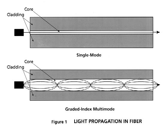
Single-mode
fiber has a smaller
core -- only 9 microns in diameter - and only 6 times the wavelength
of light it transmits. The small core size limits the transmitted
light in the fiber to only one principle mode, which minimizes
dispersion of light pulses, increasing the distance the signal
can be sent.
Multimode
fiber has a large core
diameter compared to the wavelength of the transmitted light 50
or 62.5 microns. Therefore, multimode fiber propagates more than
one mode of light. With its relatively large core, multimode fiber
suffers more dispersion than singlemode. Using a graded index
core, where layers of light have lower index of refraction as
you go further from the center of the core, minimizes dispersion
but complicates the manufacturing process.
There are two
main steps in the
process of converting raw materials into optical fiber ready to
be shipped:
1. manufacturing of the pure glass preform and 2. drawing of the
preform
Manufacturing
The Preform
The first
step in manufacturing
glass optical fibers is to make a solid glass rod, known as a
preform. Ultra-pure chemicals -- primarily silicon tetrachloride
(SiCl4) and germanium tetrachloride (GeCl4) -- are converted into
glass during preform manufacturing. These chemicals are used in
varying proportions to fabricate the core regions for the different
types of preforms.
The basic
chemical reaction of
manufacturing optical glass is:
SiCl4 (gas) +
O2 > SiO2 (solid)
+ 2Cl2 (in the presence of heat)
GeCl4 (gas) +
O2 > GeO2 (solid)
+ 2Cl2 (in the presence of heat)
The core
composition of all standard
communication fibers consists primarily of silica, with varying
amounts of germania added to increase the fiber's refractive index
to the desired level. Single-mode fibers typically have only small
amounts of germania and have a uniform composition within the
core. Multimode fibers typically have a much higher refractive
index, and therefore much higher germania content. Also, the core
composition and the refractive index of graded-index multimode
fibers changes across the core of the fiber to give the refractive
index a parabolic shape.
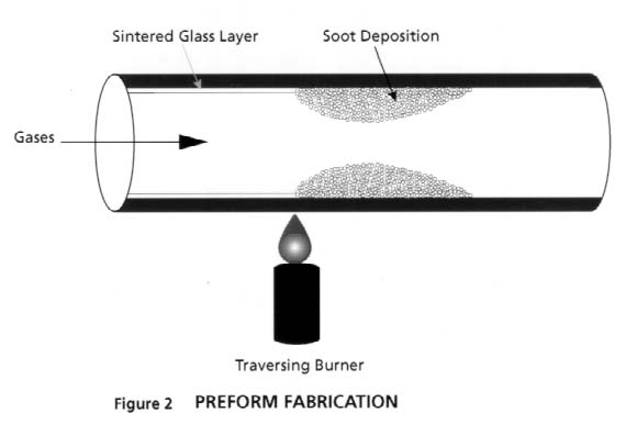
There are
several methods used
to manufacture preforms. In the Modified Chemical Vapor Deposition
(MCVD) process, the highly controlled mixture of chemicals described
above is passed through the inside of a rotating glass tube made
of pure synthetic SiO2.
The pure silica tube is mounted on a lathe equipped with a special
heat torch. As the gasses flow inside the tube, they react to
the heat by forming solid submicron particles, called "soot,"
in the vicinity of the heat zone. Once the soot is formed, it
is deposited on the inner wall of the tube. As the burner traverses
over the deposited soot, the heat transforms these solid white
particles into pure, transparent glass, in a process called
vitrification.
The deposited material will form the core region of the optical
fiber( see Fig. 2 for a schematic diagram of the process.)
.
The process
is repeated for many
hours as each subsequent core layer is formed. For every sweep
of the burner, the manufacturer can modify the composition, viscosity
and thickness of the deposited layer in order to produce specific
fiber designs. This, in conjunction with the ability to change
the speed at which the burner moves and the temperature of the
flame, gives us the ability to manufacture a wide range of ultra-pure
optical fiber types.
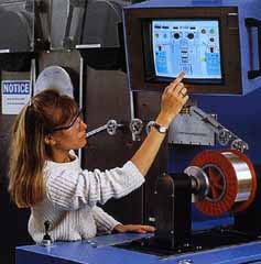
The precise
delivery of chemicals
is ensured through the design of manufacturing equipment that
performs accurately and consistently. For example, mass flow
controllers
are used to meter chemicals for the reaction. All critical process
parameters are monitored and controlled in real time by on-line
computers that are also programmed to collect all pertinent process
data.
After the
desired amount of core
material is deposited the chemical flow is eliminated, the speed
of the torch is decreased and the temperature of the flame is
increased so that the tube collapses into a solid rod. At the
end of this process, an operator separates the preform from the
rest of the glass assembly and moves it to the next step. The
entire preform manufacturing process is highly automated with
minimal human involvement.
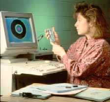
The
refractive index of the manufactured
preform is measured using a preform analyzer. This instrument
measures critical core parameters and compares them to internal
specifications. All pertinent parameters are plotted automatically
on statistical control charts that the operators review for every
measurement.
The pure
silica glass starting
tube has become part of the cladding region of the preform. The
cladding region is further increased by the "sleeving"
or "overcollapse" process. Here, another pure silica
tube is collapsed on the outside of the original preform, bringing
the geometrical dimensions of the preform to final specifications.
Another
process used is Outside
Vapor Deposition (OVD), where the soot is deposited on the surface
of a "bait rod" made of pure silica. The first layers
are the core then the cladding is added. After all the layers
are deposited, the bait rod is removed and the preform is headed
and collapsed in a similar way to the MCVD process.
Drawing
The Fiber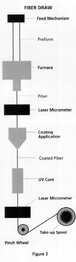
The next step
in the process of
producing optical fibers is to convert the manufactured preform
into a hair-thin fiber. This is done in an operation called fiber
draw (Fig. 3). The tip of the preform is lowered into a high-purity
graphite furnace. Pure gasses are injected into the furnace to
provide a clean and conductive atmosphere. In the furnace, tightly
controlled temperatures approaching 1900°C soften the tip
of the preform. Once the softening point of the preform tip is
reached, gravity takes over and allows a molten gob to "free
fall" until it has been stretched into a thin strand.

The operator
threads this strand
of fiber through a series of coating dies, and the drawing process
begins. The fiber is pulled by a tractor belt situated at the
bottom of the draw tower and then wound on winding drums. During
the draw, the preform is heated at the optimum temperature to
achieve an ideal drawing tension. Draw speeds of 10 - 20 meters
per second are not uncommon in the industry.
During the
draw process the diameter
of the drawn fiber is controlled to 125 microns within a tolerance
of only 1 micron. A laser-based diameter gauge is used to monitor
the diameter of the fiber. The gauge can sample the diameter of
the fiber at rates in excess of 750 times per second. The actual
value of the diameter is compared to the 125 micron target. Slight
deviations from the target are converted to changes in draw speeds
and fed to the tractor mechanism for correction. If the diameter
of the fiber increases above its target, the drawing speed is
increased; if the fiber diameter starts falling below the target,
the draw speed is decreased. Typically, 125 micron diameter control
is achieved within a six sigma interval of the 1 micron tolerance.
A two layer
protective coating
is then applied to the fiber -- a soft inner coating and a hard
outer coating. This two-part protective jacket provides mechanical
protection for handling while also protecting the pristine surface
of the fiber from harsh environments. These coatings are cured
by ultraviolet lamps. The drawing process is well automated and
requires virtually no operator interaction after the threading
step.
Test
and Measurement
The drawn
fiber is next tested,
where all optical and geometrical parameters are checked to ensure
that they meet stringent requirements.
First, the
tensile strength of
the fiber is tested. Each spool of drawn fiber is wound through
a series of capstans and subjected to loads to ensure that the
fiber has the minimal tensile strength specified. The fiber is
then spooled onto shipping reels and cut to specified lengths.
The fiber is
tested for point
defects with an Optical Time Domain Reflectometer (OTDR), which
uses scattered light to indicate the location of any anomalies
along the length of the fiber.
The spooled
fiber is automatically
tested for transmission paramters including:
- attenuation:
decrease in signal strength over distance
- bandwidth:
information-carrying capacity; an important measurement for multimode
fiber
- numerical
aperture: the measurement of the light acceptance angle of a fiber
- cut-off
wavelength: in single-mode fiber the wavelength above which only a
single mode propagates
- mode
field diameter: in single-mode fiber the radial width of the light
pulse in the fiber; important for interconnecting
- chromatic
dispersion: the spreading of pulses of light due to rays of different
wavelengths traveling at different speeds through the core; in
single-mode fiber this is the limiting factor for information carrying
capacity
In addition,
both multimode and
single-mode fibers are measured for many geometrical parameters
including:
- cladding
diameter
- cladding
non-circularity
- coating
outer diameter
- coating
outer non-circularity
- coating
concentricity error
- core-clad
concentricity error
- core
non-circularity
- core
diameter
Environmental
and mechanical testing
is also performed periodically to ensure that the product maintains
its optical and mechanical integrity and complies with customer
requirements. These tests include:
- coating
strip force
- operating
temperature range
- temperature
dependence of attenuation
- temperature-humidity
cycling
- accelerated
aging
- water
immersion
Finally, the
tested fiber is ready
for cabling to protect the fiber and then installation.
Thanks
for information and
photos to
O F S, formerly
Lucent Technologies, which manufactures and markets high-performance
multimode optical fibers for data communication applications worldwide.
Visit O F S's Web site at http://www.ofsinnovations.com/
Return To The
FOA
Home Page
Return To FOA
Tech Topics