
| Measuring
Reflectance or Return Loss Reflectance Reflectance (which has also been called "back reflection" or optical return loss) of a connection is the amount of light that is reflected back up the fiber toward the source by light reflections off the interface of the polished end surface of the mated connectors and air. It is also called fresnel reflection and is caused by the light going through the change in index of refraction at the interface between the fiber (n=~1.5) and air (n=~1). Reflectance is primarily a problem with connectors but may also affect mechanical splices which contain an index matching gel to prevent reflectance.  Optical return loss (ORL) is sometimes used as meaning the same as reflectance but, as the inverse of reflectance, has the opposite sign, e.g. -50dB reflectance is 50dB return loss. However, the term has been adopted by OTDR manufacturers to mean something different - the total of all reflectance events and total fiber backscatter over the entire length of fiber being tested. See below for how OTDRs measure reflectance and return loss. Connectors have different ferrule end finishes to reduce reflectance as well as loss. Mechanical splices have index matching gel to prevent reflections. Properly made fusion splices will have no refelctance; a reflectance peak indicates incomplete fusion or inclusion of an air bubble or other impurity in the splice. Reflectance is one component of the connector's loss, representing about 0.3 dB loss for a non-contact or air-gap connector where the two fibers do not make contact. Minimizing the reflectance is necessary to get maximum performance out of high bit rate laser systems and especially AM modulated CATV systems. In multimode systems, reflections are less of a problem but can add to background noise in the fiber. Since this is more a problem with singlemode systems, manufacturers have concentrated on solving the problem for their singlemode components but multimode connectors benefit also since any reduction in reflectance also reduces loss. Several schemes have been used to reduce reflectance, mainly using a convex physical contact (PC) polish on the end of the connector ferrule, which reduces the fresnel reflection and reduces reflectance to ~-40 to -50 dB. The technique involves polishing the end surface of the fiber to a convex surface to ensure proper fiber contact. On singlemode fiber, PC finishes work even better at a slight angle (8º) to almost totally prevent reflectance (~ -60 dB). These connectors are called APC or angled physical contact connectors. Reflectance is defined by the amount of light reflected compared to the power of the light being transmitted down the fiber. Thus a 1% reflectance is -20 dB, which is about what you get from a flat polished air gap connection, and 1 part per million would be -60 dB, typical of an APC connector. Return loss is the opposite, the amount of loss at the level of the return signal, so -20 dB reflectance is 20 dB return loss. Measuring Reflectance There are two ways to measure reflectance. One method uses a source and power meter with some accessories or an instrument called an optical CW reflectometer (OCWR), while the other method uses an optical time domain reflectometer ( OTDR.) Neither method is particularly accurate, about +/-1 dB at best, but test equipment manufacturers often have readouts to 0.01 dB which only confuses people who think that the resolution of the instrument is the accuracy of the measurement. The problem with reflectance is the large range of the measurement which causes one of the two measurements to be a very low optical power. Typical reflectance measurements require a large dynamic range, since reflectance is small for most current types of connectors as shown in the table below.
Measuring over a 40 to 60 dB range is challenging, and reflectance testing adds another problem, how to minimize the errors from other reflecting parts of the cable being tested or even fiber backscatter on longer fibers. Furthermore, reflectance is sensitive to polarization effects which may not be controllable in all test conditions. Note: Reflectance is incredibly sensitive to cleanliness of the mating surfaces of the connectors. Before testing, always inspect, clean and inspect connectors again to ensure perfectly clean connectors. OCWR Testing Below is a diagram of a typical setup for reflectance or return loss tests of connectors or patchcords per industry standards (TIA FOTP-107 or IEC 61300-3-6) using a light source and power meter. This test is typically used for terminated patch cords when the loss and reflectance values are required specifications. The method sends light from a source through a coupler to the connection that is being tested. That connection will typically consist of a reference connector which is used to mate to the connector under test. The light reflected from that connection is split by the coupler and part is measured by the power meter. 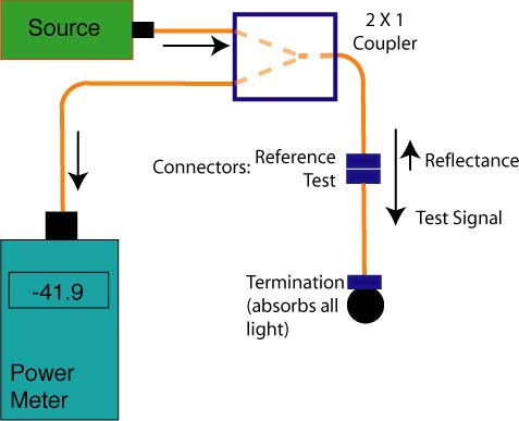 In order to calculate the reflectance or return loss, you need to know the magnitude of the test signal and the split ratio of the coupler, including the excess loss of the coupler. The coupler will reduce the outgoing and reflectance power levels by 3 dB plus some loss due to its inefficiency, typically ~ 3.5 dB.. You must also minimize the reflectance of other components in the cable under test. There are two ways often used to "terminate" or reduce the reflectance from the rest of the cable under test. One method is to use an "optical termination" at the end connector, typically done by inserting the end of the connector ferrule into an index matching gel or liquid. The index matching gel used for mechanical splices works well, but mineral oil or alcohol works fairly well too. After the test, of course, the connector ferrule needs careful cleaning with pure isopropyl alcohol. 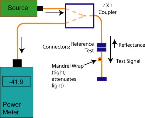 The other method to use for singlemode fiber is to use a very tight mandrel wrap - abot 10 turns on a 1/4" or 6 mm mandrel. This should attenuate the signal enough that the reflections from additional components will be minimized. (Remember the light will be attenuated in both directions, so if you introduce a 30 dB loss, the total loss will be 60 dB.) This method only works on singlemode fiber and has some drawbacks. It may leave the cable jacket stretched out more than it can recover from, so the cable will always look bad in the area where the mandrel wrap was done. It will not work on patchcords made from "bend-insensitive" fiber. Here is the 1-2-3 of making OCWR reflectance tests. First determine the power level of the test souce. It needs to be fairly powerful if you expect to measure low reflectance. Attach a power meter to the test connector and measure the power level. For this example, let's say it is 0 dBm. 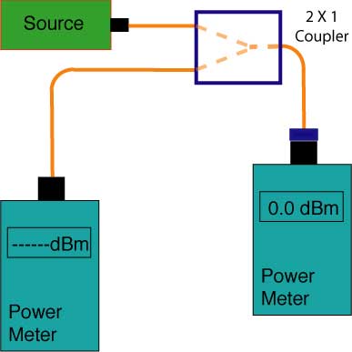 Next you need to terminate the test connector and determine the "noise floor" for the measurement which can include contributions from the coupler and any other devices in the test setup. At -60 dBm, we have a low power level for noise, but it could be a problem if we tried to check APC connectors. 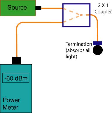 Now attach your device to test to the reference connector. Terminate the far end using either index matching gel or the mandrel wrap method (which is necessary on a long cable which has not only reflectance but backscatter to consider. This is why this is a patchcord test, as long cables are not possible to test this way.) 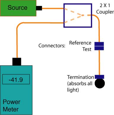 The power meter reads -41.9 dBm. We need to calibrate the measurement for the coupler, let's add 3.5 dB, so we have -38.4 dB down from the 0 dBm test signal or a reflectance of -38.4 dB (ORL 38.4 dB.) Since Our noise floor was -60 dBm, or ~ 1% (-20 dB) of the reflectance we measured, we can ignore it. OCWR and Long Cables The OCWR technique is really designed to work on patchcords. Since the natural backscatter of the fiber adds to the measured reflectance, longer cable runs will include a significant amount of backscattered light. There are instances where the total of all reflectances and backscatter is called "optical return loss" (ORL) and is measured as a indicator of the effect of the cable plant on laser transmitters. Some OTDRs can also calculate ORL for this same definition. Reflectance Testing By OTDR The OTDR can measure the amount of light that's returned from both backscatter of the fiber and reflected from a connector or splice, leading to two independent tests, reflectance and optical return loss. Reflectance At An Event The amount of light reflected at a joint between two fibers is determined by the differences in the index of refraction of the two fibers joined, a function of the composition of the glass in the fiber, or any air in the gap between the fibers, common with terminations and mechanical splices. Generally speaking, connectors will show reflectance peaks on OTDR traces, mechanical splices may show reflectance peaks and fusion splices will show no reflectance. 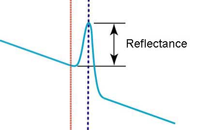 In an OTDR, the peak that identifies a reflective event is measured and reflectance calculated. Higher peaks indicate higher reflectance. In order to measure reflectance, the peak must not saturate the OTDR receiver, indicated by a flat-topped reflectance peak (below.) For instance this is an OTDR trace where reflectance cannot be accurately measured. It will only indicate a value less than actual. 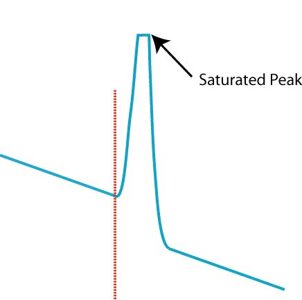 Calculating reflectance in an OTDR is a complicated process involving the baseline of the OTDR, backscatter level and power in the reflected peak as shown in the diagram below. Since reflectance is defined as a fraction of the power in the test signal, the OTDR must calculate the test power from the backscatter level of the fiber, based on the typical backscatter coefficient of the fiber being tested. 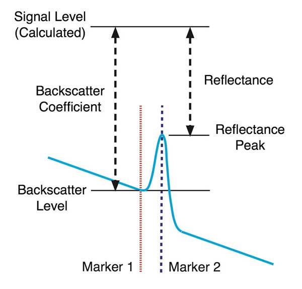 The OTDR measures the backscatter level just before the peak being measured, applies a correction for the pulse width of the OTDR test pulse, then calculates the test signal level. It then measures the power of the refelctacne peak and calculates the reflectance. The indirect way this is measured causes reflectance measurements with an OTDR have a fairly high measurement uncertainty, but have the advantage of showing where reflective events are located so they can be corrected if necessary. By choosing the reflectance measurement and putting the right (blue) cursor on the peak of the reflection and the left (red) cursor just to the left of the reflection, the OTDR will measure the reflectance. Optical Return Loss (ORL) The OTDR generally tests ORL by calculating the total all the light reflected from reflective events plus the total backscatter from the entire length of fiber being tested. This ORL measurement is sometimes used as a specification for very high speed systems as ORL can be a contributor to noise in a transmission link. It is not a reflectance test of an individual event and should not be confused with that test. More information on OTDRs. Return to the Table of Contents of the FOA Online Reference Guide. |
|
|