
Testing Fiber Optic Couplers, Splitters Or Other Passive Devices
Testing these devices as components is the subject
of this page. Testing networks with both an optical loss test set
(OLTS) or OTDR is covered in other pages on Testing FTTH PONs and Testing Passive OLANs. First we should define what these passive devices are. An optical coupler is a passive device that can split or combine signals in optical fibers. They are named by the number of inputs and outputs, so a splitter with one input and 2 outputs is a 1X2, and a PON splitter with one input and 32 outputs is a 1X32. Some PON splitters have two inputs so it would be a 2X32. While 1:n or 2:n couplers are most common, there are n:n couplers also, e.g. 8:8 with 8 inputs and 8 outputs, which are used to create networks with n devices, like 8 in this case, allowing all devices to talk to each other. These devices are generally bidirectional. With a 1:n device, in one direction they split the signal into n ports/fibers and into the other end they combine the signals into one port/fiber. Passive optical networks generally use 1:n or 2:n splitters to connect multiple users to a single electronic port in a optical network terminal. Since these are the most popular styles for networks today. they will be used as examples. The specifications for a splitter are loss across the device and the variability of that loss for each port. A well made splitter will have low excess loss and low variability. The process of splitting the input signal induces loss; 3 dB loss is induced for each split factor of 2. Testing shows the excess loss and variability across ports. Here is a table of typical losses for splitters.
Important Note! Mode Conditioning can be very important to testing couplers. Some of the ways they are manufactured make them very sensitive to mode conditioning, especially multimode but even some types of singlemode couplers. Singlemode couplers should always be tested with a small loop in the launch cable (tied down so it does not change and set the 0dB reference with the loop.) Multimode couplers should be mode conditioned by a mandrel wrap or similar to ensure consistency. (More on mode conditioning.) Let's start with the simplest type. Shown below is a simple 1X2 splitter with one input and two outputs. Basically, in one direction it splits the signal into 2 parts to couple to two fibers. If the split is equal, each fiber will carry a signal that is 3dB less than the input (3dB being a factor of two) plus some excess loss in the coupler and perhaps the connectors on the splitter module. Going the other direction, signals in either fiber will be combined into the one fiber on the other side. The loss is this direction is a function of how the coupler is made. Some couplers are made by twisting two fibers together and fusing them in high heat, so the coupler is really a 2X2 coupler in which case the loss is the same (3dB plus excess loss) in either direction. Some splitters use optical integrated components, so they can be true splitters and the loss in each direction may different. 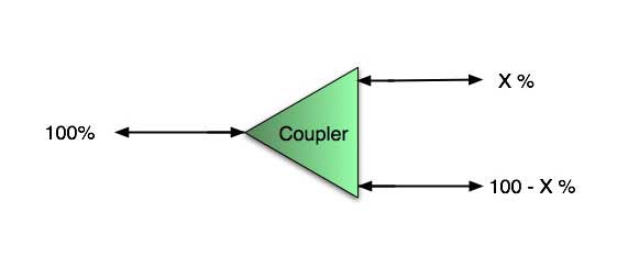 So for this simple 1X2 splitter, how do we test it? Simply follow the same directions for a double-ended loss test. Attach a launch reference cable to the test source of the proper wavelength (some splitters are wavelength dependent), calibrate the output of the launch cable with the meter to set the 0dB reference, attach to the source launch to the splitter, attach a receive launch cable to the output and the meter and measure loss. What you are measuring is the loss of the splitter due to the split ratio, excess loss from the manufacturing process used to make the splitter and the input and output connectors. So the loss you measure is the loss you can expect when you plug the splitter into a cable plant. 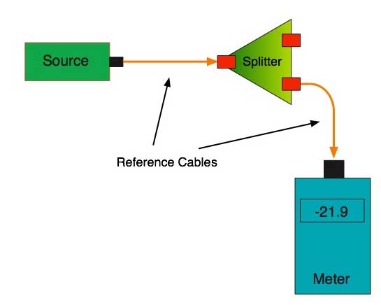 To test the loss to the second port, simply move the receive cable to the other port and read the loss from the meter. This same method works with typical PON splitters that are 1 input and 32 outputs. Set the source up on the input and use the meter and reference cable to test each output port in turn. What about the other direction from all the output ports? (In PON terms, we call that upstream and the other way from the 1 to 32 ports direction downstream.) Simply reverse the direction of the test. If you are tesing a 1X2 splitter, there is just one other port to test, but with a 1X32, you have to move the source 32 times and record the results on the meter. 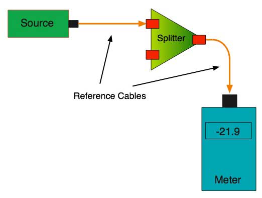 What about multiple input and outputs, for example a 2X2 coupler? You would need to test from one input port to the two outputs, then from the other input port to each of the two outputs. This involves a lot of data sometimes but it needs to be tested. There are other tests that can be performed, including wavelength variations (test at several wavelengths), variations among outputs (compare outputs) and even crosstalk (put a signal on one output and look for signal on other outputs.) Once installed, the splitter simply becomes one source of loss in the cable plant and is tested as part of that cable plant loss for insertion loss testing. Testing splitters with an OTDR is not the same in each direction, so be sure to understand how to test them by reading this page on FTTH testing. Other Passive Devices There are other passive devices that require testing, but the test methods are similar. Fiber optic switches are devices that can switch an input to one of several outputs under electronic control. Test as you would the splitter as shown above. Switches may be designed for use in only one direction, so check the device specifications to ensure you test in the proper direction. Switches may also need testing for consistency after multiple switch cycles and crosstalk. Attenuators are used to reduce signal levels at the receiver to prevent overloading the receiver. There is a page on using attenuators that you should read. If you need to test an attenuator alone, not part of a system, use the test for splitters above by using the attenuator to connect the launch and receive cables to see if the loss is as expected. Wavelength-division multiplexers can be tricky to test because they require sources at a precise wavelenth and spectral width, but otherwise the test procedures are similar to other passive components. Here is a complete review of all standard methods of testing fiber optic components. Here are the FOA Standards for testing fiber optic components. |
||||||||||||||||||||||||
| (C)2019-23, The Fiber Optic Association, Inc. |