
| Bend-Insensitive
Fiber Optical fiber is sensitive to stress, particularly bending. When stressed by bending, light in the outer part of the core is no longer guided in the core of the fiber so some is lost, coupled from the core into the cladding, creating a higher loss in the stressed section of the fiber. If you put a visible laser in a fiber and stress it, you can see the light lost by the stress as in this multimode fiber. 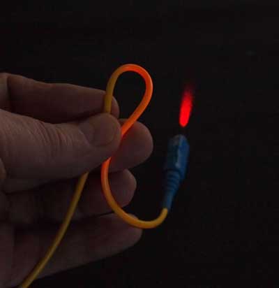 Fiber coatings and cables are designed to prevent as much bending loss as possible, but it's part of the nature of the fiber design. Bending losses are a function of the fiber type (SM or MM), fiber design (core diameter and NA), transmission wavelength (longer wavelengths are more sensitive to stress) and cable design. In 2007, a new type of "bend-insensitive" singlemode fiber was introduced, followed by multimode fiber in 2009. Manufacturers liked to demonstrate this fiber by bending it around impossibly small bends or stapling it to a piece of wood - demonstrations that made veterans of the business cringe at seeing fiber treated so badly! But the demonstrations showed that these fibers could be bent in what seemed like impossibly small radii without significant light loss, although skeptics still wondered about the long term effects of this kind of abuse on reliability. Once the patents were filed, manufacturers were more willing to explain what they had done to make these fibers so tolerant to tight bends. An optical "trench" - the term used for a ring of lower index of refraction material - was built into the fiber to basically reflect the lost light back into the core of the fiber. It turns out, the design was similar to a type of singlemode fiber called "depressed cladding" fiber that was first introduced in the late 1980s. And in 2009, manufacturers introduced multimode fibers that showed using using a similar technique could also improve bending loss in multimode fiber. Let's examine the design of bend-insensitive multimode fiber (which we will usually call by its acronym BI MMF) that shows the technique. 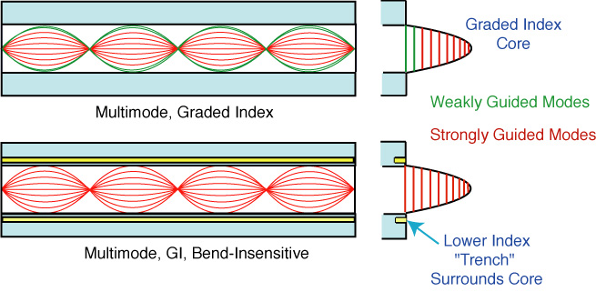 In regular graded index multimode fiber, there are many modes (or rays of light - about 400 of them) being transmitted down the fiber. The inner modes are "strongly guided" which means they have little sensitivity to bending stresses. But the outer modes are "weakly guided" which means they can be stripped out of the core when the fiber is bent. Bend-insensitive fiber adds a layer of glass around the core of the fiber which has a lower index of refraction that literally "reflects" the weakly guided modes back into the core when stress normally causes them to be coupled into the cladding. Some early singlemode fibers (depressed-cladding fibers) used a similar technology to contain the light in the core of the fiber but this design has a much stronger effect. The trench, or moat as some people call it, surrounds the core in both BI SMF and BI MMF to reflect lost light back into the core. The trench is just an annular ring of lower index glass surrounding the core with very carefully designed geometry to maximize the effect. See the red ring around the core on this fiber drawing. 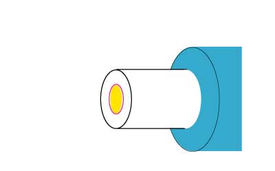 When you look at the end of a bend-insensitive fiber in a microscope with angled lighting, you can sometimes actually see the trench as a gray ring around the core. 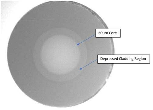 File
courtesy of Panduit File
courtesy of PanduitAnd here are two fiber comparisons from the field. The BI fiber is the more complex structure on the right. 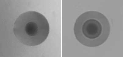 50/125 MMF, regular (L) and bend-insensitive (R) 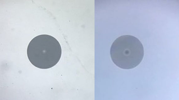 SMF, regular (L) and bend-insensitive (R) Bend-insensitive fiber (or BI fiber as it is now called, even BI MMF or BI SMF) has obvious advantages. In patch panels, it should not suffer from bending losses where the cables are tightly bent around the racks. In buildings, it allows fiber to be run inside molding around the ceiling or floor and around doors or windows without inducing high losses. It's also insurance against problems caused by careless installation. BI fibers are available in 50/125 MM (OM3 and OM4) and SM versions. Considering the advantages of BI fiber and the small incremental cost to manufacture it, some manufacturers have decided to make all their 50/125 MM fiber bend-insensitive fiber. Many applications for BI SM fiber are in premises installations like apartment buildings or for patchcords, where it simplifies installation and use. BI SMF is also used in OSP cables since it allows fabrication of smaller, lighter high fiber count cables. Another application for BI fibers is microcables and high fiber count cables. By reducing the fiber's sensitivity to stress, one can make the buffer diameter smaller (200 instead of 250 microns) and squeeze more fibers into smaller cables. This has led in two directions. Microcables are simply like loose tube cables shrunken to really small sizes, about half the size of conventional cables. This 144 fiber cable is about the size of a pencil. 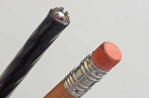 The other use for BI fibers is is make cables with as many fibers as possible. This has led to cables with 1728 fibers like this one from Prysmian as well as 3456 and 6912 fibers. 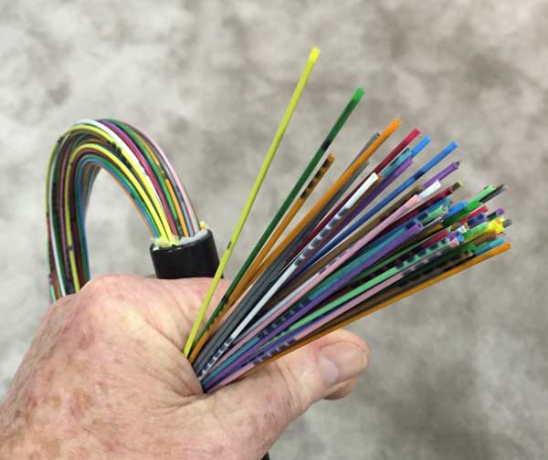 Compatibility With Conventional Fibers One question that often arises is are these fibers compatible with regular fibers. Can they be spliced or connected to other conventional (non-BI) fibers without problems? How does the inclusion of higher order modes affect bandwidth? That answer seems to be yes for all SM fibers. Since only one mode is guided in the core, the trench has a minimal impact on system performance and measurement. It seems you can mix and match regular and BI SMF fibers with no problems. For MM fibers, it is less clear. Measurement of core size, NA, differential mode delay (DMD) and bandwidth were developed prior to the introduction of BI MMF designs. These measurements are in the process of being evaluated and updated so measurement results may depend on the manufacturer of the BI MMF. For the most part, it appears that BI MM fiber can be made to be compatible to other non-BI fibers by modifying the core design slightly or careful engineering of the trench surrounding the core, but at this point it is left to the manufacturers to show their product will perform equivalently to the installed base of fiber. When short lengths of BI MMF are measured, they may have a larger effective NA and core size than conventional MM fibers since they propagate "leaky modes" that are attenuated in conventional fiber designs. This may affect splice or connector loss when mating BI MMF with conventional MMF but usually only in one direction, from BI MMF to conventional MMF, in a manner similar to the losses from mismatched fibers. One approach to make BI MMF compatible with non-BI fibers is to modify the core index profile slightly to reduce the higher order modes to make them compatible to conventional fibers without otherwise materially affecting the performance of the fiber. A second approach is to leave the core index profile alone but carefully engineer the trench to produce the bend-insensitivity. If you want to read more on the past controversy about compatibility of BI MM fibers, see the FOA Newsletter for February, 2011. Testing Testing BI MM fibers or using them for reference cables for testing is another matter. Most multimode fiber testing standards call for modal conditioning, often using a mandrel wrap mode filter (http://www.thefoa.org/tech/ref/testing/test/MPD.html). The mandrel wrap specified in most standards doesn't affect BI fibers the same way as conventional fibers, so either special sources or very small mandrels are required. The encircled flux standard for modal fill which is being adopted by many new standards may address some of these concerns. 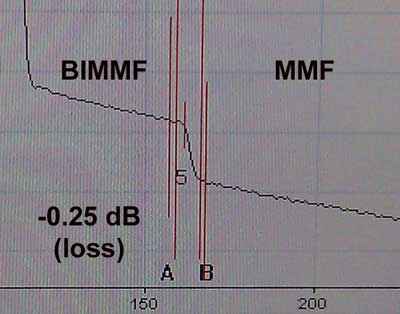 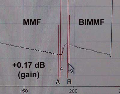 Another problem arises when testing mixes of BI MM and conventional fibers with an OTDR. Some BI fiber has a larger scattering coefficient than regular fibers and can create large directional loss differences when testing splices or connectors with an OTDR, causing gainers in MM fiber OTDR tests, a major confusion. This issue has not been addressed yet by all fiber manufacturers or standards, so check with your fiber supplier. We covered this issue in the FOA Newsletter for February, 2012. Always check with your fiber vendor for their recommendations. FOA thanks three major manufacturers of optical fiber for their contributions to this page. Table of Contents: The FOA Reference Guide To Fiber Optics |
|
|