
NetworksYou can also watch the FOA YouTube videos on networks What Is A Network? A network is basically a group of interconnected devices that share bandwidth and communicate with each other and probably devices in other networks too. Connections allow sending messages, sharing files and working in unison. The devices need a way to connect to each other first, with what is called a "physical layer" consisting of cable - copper or fiber- or radio - wireless. The physical layer can have several different architectures or connection schemes, generally called a a bus, ring or star. Then there are rules on how the devices identify themselves and share the bandwidth, and that's the basis of the network protocol. Here is an example of a network, a corporate LAN connected to the Internet. The black line between Internet | LAN in the drawing below shows the boundary between the LAN and the Internet - to the right > is the LAN and to the left < is the Internet. Remember the essence of a network like this is that any users can connect to any other user or any source of data on the network. Users (U) connect to the network by wireless to WiFi access points (W, on the dotted lines) or cables (solid lines) to the LAN switches (S). Switches can be layered to connect all users to the network. The LAN usually has some central storage (S, usually disk drives) and servers (C) to connect users to the storage to access data. If the corporate LAN servers and storage are large enough, they will be called a data center. At some point, the LAN has a switch that connects to a router (R) or routers that connect to the Internet, providing an Internet connection to users and allowing other networks like this one to communicate with each other. The Internet is connected on special switches called routers that have connections to multiple routers creating a mesh network. Routers are smart so they can find the best way to connect any two points on the Internet. In the real world, multiply this diagram by millions of times. 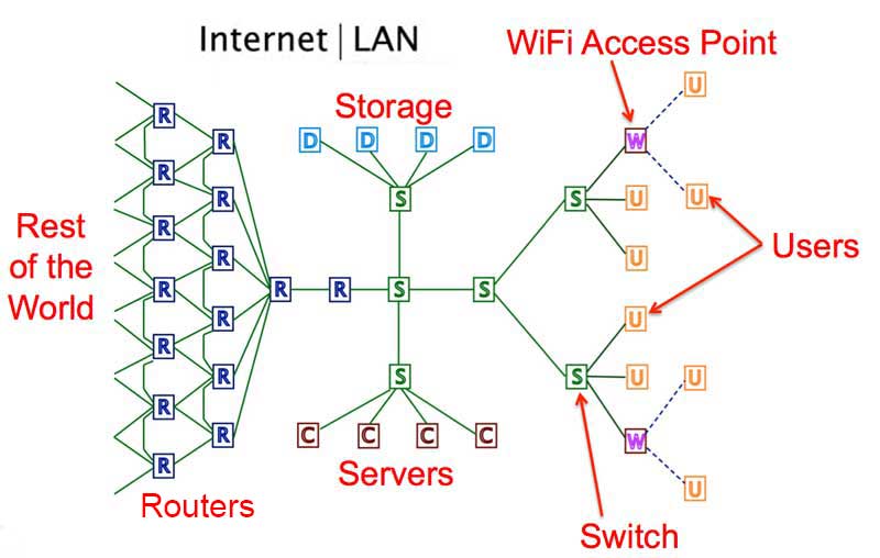 All the devices in a network share the connections as they communicate with each other. One factor that is invariable is the sharing means that the total available bandwidth of the network is shared by the connected devices and is not available simultaneously to all devices. The possible exception is multiplexing schemes like wavelength-division multiplexing in fiber optics but WDM is actually separate networks using the same fiber infrastructure at different wavelengths. So a network is connected devices sharing bandwidth. Since they are sharing the network, they need unique identification, a way for one device to connect with another, a unique address to send communication from and to. They need rules for gaining access to the network to send messages without interfering with other messages or having their message interfered with. They need rules on how the data is formatted for transmission and transmitted on the network medium. Those rules are called the network protocol. Several types of protocols are used. In a plain old telephone system (POTS), one phone was physically connected to another- literally in the early days operators patching wires at a switchboard, then through mechanical switches and finally electronic switches. This is called circuit switching. Switching electronically was done according to preprogrammed routines to efficiently allocate bandwidth along any given route and have alternatives if a route was busy. 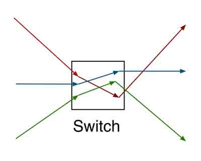 With the advent of digital phone systems, speeds were high enough that on top of physical switching, one could share a connection among many users by allocating a time slot on the connection of a faster network. A digitized phone call required only 64 kilobits per second. An early T1 phone line at 1.544 Mb/s could multiplex 24 calls at once. I will leave it as an exercise for the reader to figure how many calls a 10 gigabit/second phone link could carry! This is called "time-division multiplexing" (TDM - to introduce one of many TLAs (three letter acronyms) that will be used here.) In the drawing below, note that the red signal has time slot 1 and 2, green 2 and 5, so this example is how a single connection shares bandwidth with 3 signals. Many more time slots are possible. Note also it's synchronized, a signal is allocated a repeating time slot to guarantee its connection as long as the two communicating devices are connected. 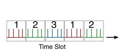 The combination of physical switching and TDM was called "time-space-time"switching - TST for short. But TST was still inefficient. If there was silence on a phone call, the system still transmitted bits, even though there was no useful content to transmit, tying up otherwise useful bandwidth. Along with data representing the digitized voice signal, every system needed to transmit data on addressing plus bits needed to synchronize the network. This overhead could use lots of valuable bandwidth. ATM, one phone protocol, had ~30% overhead. Others require time to process and encapsulate packets for transmission through networks using incompatible protocols. At one point Google declared that they only transmitted IP-Internet Protocol, reducing the overhead and latency - plus the power consumed in processing packets - along their networks. CATV - which means "community antenna TV" not "cable TV" - used a different multiplexing scheme to put many channels on one cable. They assigned a frequency to each channel just like broadcasting over the air, creating frequency division multiplexing or FDM. Digital data can be transmitted the same way by converting signals to frequency modulation or FM. This method was originally called "broadband" which can be confusing considering the current meaning which refers to any high speed connection. 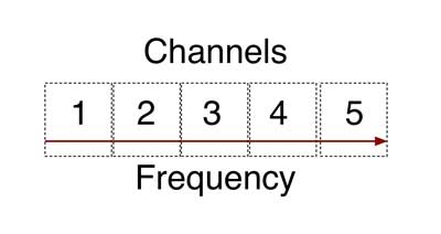 It was not long after computers became available that users wanted them to talk to multiple peripherals and other computers in the office, thus was developed the local area network or LAN. The first networks used simple switching protocols like the phone system. That worked fine with a few devices connected to the network, but once minicomputers became common and PCs began being connected to networks, more efficient and faster methods were necessary. In the mid-70s, Xerox Palo Alto Research Labs invented Ethernet with a new type of protocol. All connected devices shared a coax cable data bus - the "ether." 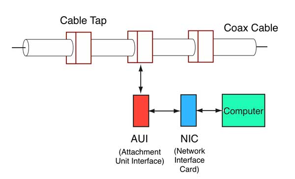 Rather than switch onto the network, a connected device would simply listen for traffic. If it heard none, it would transmit its message which was called a data packet. If two devices did so simultaneously, causing a collision, they would stop, wait a random time and try again. Like everything techie, this has a catchy acronym, CSMA/CD for "carrier sense multiple access with collision detection." Unlike telephone connections, Ethernet packets are asynchronous. They do not require synchronous transmission like a phone network does for quality voice transmission. A packet of data is sent and a confirmation of receipt is returned. If there is more data to be sent, it goes in another packet until the entire data set is transmitted. The problem with the Ethernet protocol was traffic. More connected devices means more collisions which means wasted bandwidth. With enough devices, one could not guarantee a device would ever get to send its data, a big problem for systems where some devices need priority, for alarms, for example. The solution is for the network to work faster - bandwidth, as we shall see, solves most network problems. By the mid-1980s, a new connection architecture was being used to implement the Ethernet bus structure, but it was done with a "star" architecture and cabling system. Basically a coax bus is where each connected device is connected to the same physical cable so each device can listen to all the traffic. The star architecture adopted to replace the coax bus was a switched star, where each device was connected to a hub, which was simply a repeater. By repeating the incoming signal to all connected devices, it could use the same protocol as the coax bus where all devices listened to the network all the time. A star with a hub had the same traffic problems that a coax bus had, collisions between data packets. So somebody got the idea of changing to a switch, back to the phone idea, where the switch looked at the address the data packet was being sent to and only used the proper links, keeping others open for other traffic. That was much more efficient. 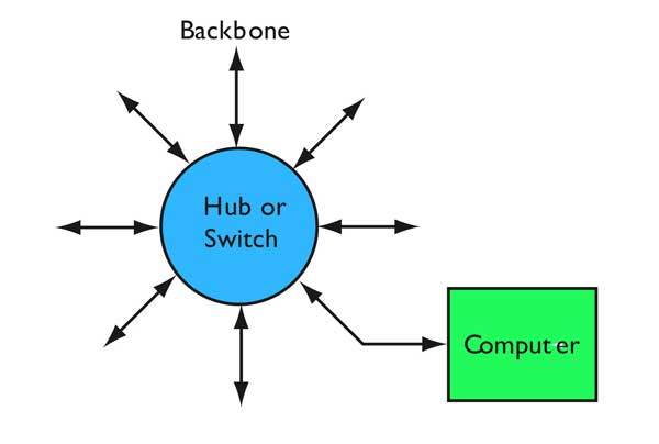 IBM tried a different method. It connected devices in a ring. Each device would be granted access to the network by receiving a "token"- a data packet that gave permission to transmit data. Once finished transmitting, the device would release the token to the next user. Thus access to the network was guaranteed, but the overhead was higher. Logically enough, IBM's network was called IBM Token Ring or TR. The token guaranteed access, so token ring was called a deterministic network. The token ring idea was used for the first all-fiber network, FDDI (Fiber Distributed Data Interface). FDDI was a 100Mb/s network with a dual counter-rotating ring for redundancy and reliability. The ring architecture was versatile. You could have dual-attach stations (DAS) connected to both rings, single-attached stations (SAS) connected to one ring through a concentrator. 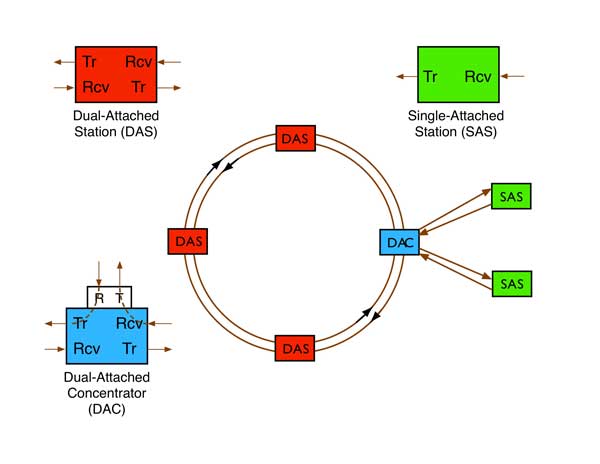 So now we have three examples of networks, TST, CD/CSMA and TR. All are designed to allow users to share the available bandwidth of the network. The phone system created another type of network, an extension of the traditional phone network that started as a star network but interconnected switches to create alternate routes for traffic, That allowed management of traffic, switching traffic from busy routes to less congested ones, but also provided a more survivable network with multiple alternative routes. That is usually called a "mesh" network. 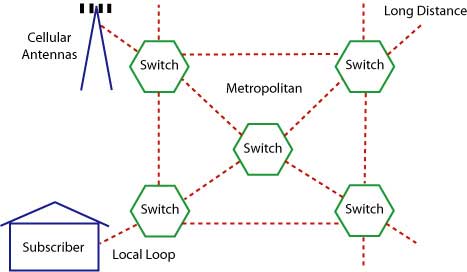 Telephone network 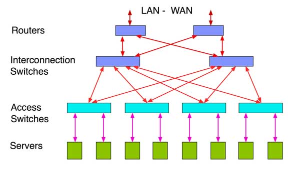 Data center architecture That same architecture was adopted by the Internet and data centers. The Internet added another protocol, Internet Protocol or IP, another packet-switched network. IP mainly differed by how addressing and switching are handled. The Internet was designed as a "mesh" network, with each switching unit connected to many others. When a packet reaches a switch, the switch has no fixed way of transmitting that packet along any route. Instead, it checks with other switches, now called routers, to find where the destination is and how to reach it. Routing allows for a more flexible network and a survivable one, since if a router fails, any others can carry the same message to its destination. You also don't get busy signals. Data is broken into packets. Packets are individual batches of digital data with source and destination information, the data and some bits that are used to check to see if the data has been transmitted error-free. The source breaks the message into packets and the receiving device uses the information in the packet to reassemble it. Thus data may be transmitted without regard to its meaning. Data, video or even voice may be broken into packets and transmitted using IP. Voice over IP (called VoIP) was troublesome at first. For voice to be transmitted with good audio quality, it needs to only be digitized at 64kb/s, very low bandwidth, but it needs to be send synchronously. If the signals are delayed or lost, the voice becomes garbled. Many schemes were tried to fix this but bandwidth solved it best. The faster the network, the lower the latency or signal delay, so the voice signal was clearer. An interesting hybrid network has evolved recently. When telcos began installing FTTH (fiber to the home), it used a passive optic network (PON) architecture. PONs use an optical splitter to broadcast a downstream signal to all users and a collision avoidance protocol upstream. This is designed to reduce the cost of components as the downstream components in a central office are more expensive than the upstream ones which must be located at each subscriber. Because the downstream signal is sent to all users, it is encoded for each user to prevent eavesdropping. This same protocol is also being used for LANs (OLANs or optical LANs) that are proving to be much cheaper than other types of LANs. 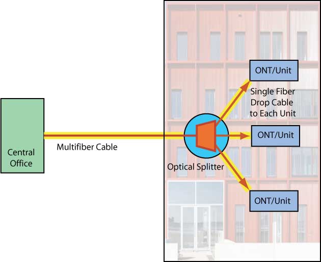 Passive optical LAN OSI (Open Systems Interconnection) Network Model These are international networking standards that separate networking into seven layers. The seven layers consist of: Layer 1 - Physical Layer (the PHY) The electrical and mechanical hardware level where the light, electrical or radio signals are transported over the network. It consists of the cabling (cable, connectors and network interface electronics). The PHY refers to anything relating to the hardware that sends and receives data. Network protocols have physical layer components like Ethernet operating over twisted pair or fiber optic cabling or wireless links. Note: A physical data structure refers to the organization of the data on a storage device. The "logical" or "virtual" data structure refers to the software, or how the information appears to the user. Layer 2 - Data Link Layer There are two sublayers: 1) Media Access Control (MAC) that controls how we access data and gives permission for its transmission. Every device connected to the network must have a unique MAC address. 2) Logical Link Control (LLC) layer that controls frame synchronization, flow control and error checking. Layer 3 - Network Layer For switching and routing to send data from node to node. It can also perform forwarding, addressing, internetworking, error handling, congestion control and packet sequencing. Layer 4 - Transport Layer For the transfer of data between systems/hosts. End-to-end error recovery and flow control ensure complete data transfer. Layer 5 Session Layer The management of connections between applications-setting up and handling of conversations, exchanges, and dialogues between applications at each end. Layer 6 Presentation Layer Here any compatibility problems are handled and "different looking" data is formatted or encrypted so that it's accepted over the network. Layer 7 Application Layer Here is where users and quality of service (QOS) are identified, and authentication and privacy occurs. This layer is application specific and it's where file transfers, e-mail, and other network software services are provided. Read more about the OSI model. Bandwidth Let's talk bandwidth. If you have a PC connected to a network over Gigabit Ethernet, do you have 1 gigabit of bandwidth to use as you see fit? Does it allow you to download large files like video at an average rate of 1 Gb/s? Not at all. You may be transmitting or receiving data at a rare of 1 Gb/s but you are on a network sharing the available bandwidth with others. You might be sharing this gigabit network with 100 users. Does that mean that your bandwidth is 1 Gb/s divided by 100 or 10 Mb/s? Not really, because network traffic is asynchronous, with bandwidth allocated to users based on timing and demand. Big data users need lots of bandwidth and small users only need a little. One of the biggest advantages of higher bandwidth is latency. The faster the connection, less time is needed to transmit data so users tie up the network for less time. If the network has less bandwidth, traffic backs up but eventually gets through, just like heavy vehicular traffic. Data, which is not inherently time-sensitive, is not corrupted by this back-up, but voice and video can be if the delay is significant. Likewise, noisy links can cause errors. Data carries flags to find errors caused during transmission and corrupted data is retransmitted. This does not work with voice or video as they require continuous data streaming. Voice or video packets with errors must be dropped and data continues streaming. Thus quality of transmission requires high bandwidth and low BER - bit error rate. Now we have another issue. Data within an enterprise network will have different rates. The "wired" devices may connect at 100Mb/s or 1000Mb/s (1Gb/s) while WiFi may be much less, depending on the implementation. But overall, data rates are likely to be higher than the connection to the outside world by the Internet. It is likely the connection to the outside world is ~10-100Mb/s, although many companies still have T1 connections at 1.544Mb/s! 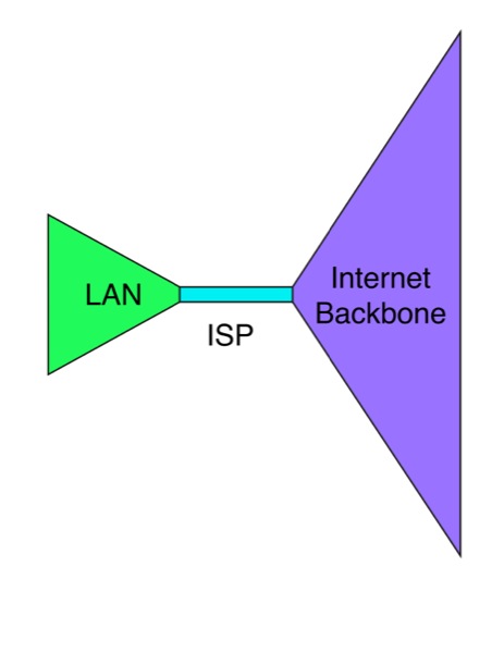 The bandwidth "funnel effect" This is not a problem for most companies using internal data centers where most of the traffic is within the corporate LAN, but the increase in video downloads and the advent of "Cloud Computing" can change the traffic patterns. Instead of data mostly flowing within the network, it must reach the data center through the Internet. If the corporate LAN has only a slow connection to the Internet, those traffic backups described above will affect data latency and voice and video quality. Thus "cloud computing" not only requires a full-time Internet connection, it requires a fast one. Likewise, the entire path data follows from point to point has high and low bandwidth sections. A metropolitan US link might be 10-100Gb/s while portions of the link in rural areas might be down to T1 rates. Routers along the line could direct the data packet one way which has higher speeds at one time then direct it through a slower link at another time. Generally speaking, high traffic routes will be built as higher bandwidth routes, but traffic patterns change, so carriers will usually be trying to catch up with network usage. That is the big problem with cellular wireless now, as smartphones have been growing and using bandwidth faster than the cellular operators can provide it by connecting towers to high speed fiber backbones. There is another solution to Internet backbone traffic problems - build more local data centers and store duplicates of all the data there so traffic is confined to a local area. This is widely done by Google for example, which represents a significant amount of Internet traffic. Netflix is another service that mirrors data locally, especially important since they can be a majority of all Internet traffic in the US in the evening. If you have ever done a speed test on your Internet connection, you have seen the speed and latency at that point in time, but have you noticed it changes? For example, we have tested both cable modem and satellite connections at our home over the course of time. In the weekday mornings, when people are away at work or school, our connection speeds are typically ~17-18 Mb/s for both services. After ~3PM, when people get home from school and work, the speed drops to ~2Mb/s, a 90% decrease! That is because of all the video entertainment downloads, where the majority of Internet traffic by consumers is video and the peak loading occurs when they are home. How does this affect users? When the traffic is high, services that require low latency like Skype or other voice over IP (VoIP) services provide poor quality connections. Video requires more local buffering at the user. How do you fix this? Prioritize services or provide more bandwidth. Another factor affects perceived network speeds, server response in data centers. Users think of network speeds in terms of how long does it take to download web pages. But web page designers are sometimes unconcerned with downloading times, loading pages with graphics and scripts that mean large numbers of files need to be downloaded - We have seen 300+ files in one page! When a server in a data center gets a request for this page, it has to hunt down all those files and forward them as separate files. Even if the web page only uses a handful of files, the time the data center servers takes to find those files, download them from servers and send them along to the requester is often the biggest delay the user sees. Tests have shown that Internet connection speeds above 10Mb/s provide little benefit for web browsing. Higher speeds mostly benefit video and to a lesser extent, VoIP. 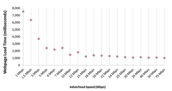 Is the Internet The Best Solution For EVERYTHING? Hardly. The different networks evolved in networks most efficient for their data formats. Telephone service worked best on a TST switched POTs network. CATV provided video best on a broadband network (meaning FM FDM (frequency division multiplexing by channels) that broadcast all channels simultaneously at different frequencies. Data flows best on IP. But enough bandwidth makes it possible for all three to share the Internet. As you can see, networks have evolved to accommodate new technology and new services, not necessarily in the most efficient way possible. Voice worked best on a switched network. Data works best in packets. Video worked best on on a broadcast model, carried over into the CATV format. Now we force everything into a packetized IP network and the only to get good quality of service is to provide lots of bandwidth. You can also watch the FOA YouTube videos on networks Table of Contents: The FOA Reference Guide To Fiber Optics |
|
|