FTTA - Fiber
To The Antenna
Today's users of
mobile devices depend on wireless connections for their
voice, data and even video communications. Even homes and
businesses may depend on wireless, especially those who
are not in urban or suburban areas served by FTTH (fiber
to the home) or FTTC (fiber to the curb.) Some of us in
the business now use the term FTTW for fiber to wireless,
since wireless depends on fiber for the communications
backbone and increasingly the connection to the wireless
antennas, no matter what kinds of wireless we use.
Wireless is not entirely wireless. The easiest way to
understand wireless is to think of it as a link that
replaces the cable that connects your cellular or wireless
phone to the phone system or the patchcord that
connects your computer or other portable Internet device
to the network. To understand wireless, it is necessary to
look at several different and unique types of wireless
systems, including cellular wireless phones, wireless in
premises cabling, municipal or private wireless links and
even some of the short distance links used for computer
peripheral connections.
This FOA page focuses on fiber to the antenna, primarily
looking at cell towers, but also antennas mounted on
rooftops, small cells and distributed antenna systems
(DAS.) Because of its variety, DAS will be covered in a
separate page in more detail.
Why fiber to the antenna?
The reason fiber is being used to connect towers and then
go up the tower to connect the antennas is consumers
insatiable desire for bandwidth. To accommodate more
bandwidth in the cellular systems, new cellular protocols
being are used (4G, LTE, and whatever comes next) but also
more antennas are needed to support more frequencies. Thus
cell towers that once had 3 antennas for coverage may have
two dozen antennas.
The increased demand for cellular bandwidth to support
fast growing data usage from smartphones and tablets
requires upgrading towers – more bandwidth means more
antennas. More antennas means more cables up the towers.
If those cables are coax, it means more weight and wind
resistance, perhaps more than the tower was designed for.
And RF (radio frequency) signals require lots of power to
transmit up the tower since the coax cable attenuates the
signals at high frequencies.
Today’s cell towers are being modified to replace older
copper coax cables with fiber optic cables to reduce
weight and cost. Like other applications of fiber, the
small size and light weight allows one fiber cable (which
often includes power conductors also) to replace many coax
cables. This diagram shows what a current cell tower looks
like. The diagram is way too complicated for a quick view
so we’ll focus on various areas of the tower to show how
fiber is used, then we’ll go into issues of installation
and testing.
Cellular Wireless
Cellular phone systems have grown to dominate the
telecommunications marketplace. Countries that have had
extensive landline phone systems for a century now already
have more cell phones than land lines. Countries that had
not developed landline-based phone networks skipped them
entirely and went directly to cellular wireless where the
adoption rates have been extremely high.
While cellular wireless started out as a voice network,
text messaging became very popular, eclipsing voice for
most users. Smart phones brought the Internet to the
phone, and soon data became the largest traffic generator
for cellular networks. In the first 3-1/2 years of the
iPhone, AT&T claimed their data traffic grew 8000% -
80 times! Now video is coming to these same devices,
creating an even faster growth rate for cellular network
traffic.
To
accommodate this traffic level, wireless needs new systems
with more radio frequency spectrum. Current systems (CDMA
for some systems, in the US, GSM for the rest of the US
and the world) are evolving into new generations of
systems (4G, LTE) that have more data bandwidth.
Almost from the beginning, cellular towers were connected
to the telco networks over fiber optics, just like any
other connection. Wireless towers have small huts at
the base that connect to fiber backbones that connect
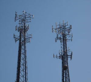
towers to the various phone companies. As traffic grows,
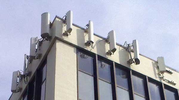
towers need more antennas. Instead of 3-4 antennas on a
tower, now one sees dozens, so towers and buildings now
look like this:
or on buildings.
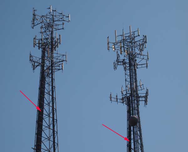
All these
antennas on a tower or the side of a building have created
another problem. In the past, each antenna has been
connected by a large (~2", 50mm) coax cable that carries
both signal and power to the antenna. But with all these
antennas, the size, weight and even wind resistance of
these cables has become a big problem, as has the cost.
These towers which have been upgraded to add many antennas
show the problem with these large coax cables.
This is
another application where copper cable is being replaced
by optical fiber. One small fiber cable can replace all
those coax cables and a separate power cable is used for
the drivers on the antennas. These applications use mostly
prefab
cable assemblies since making terminations on top of
the tower is difficult to say the least. Some applications
use prefab at the top of the tower and conventional
termination at the base. Many of these systems use
multimode fiber because the distances are so short and the
transceivers are much less expensive for MM fiber.
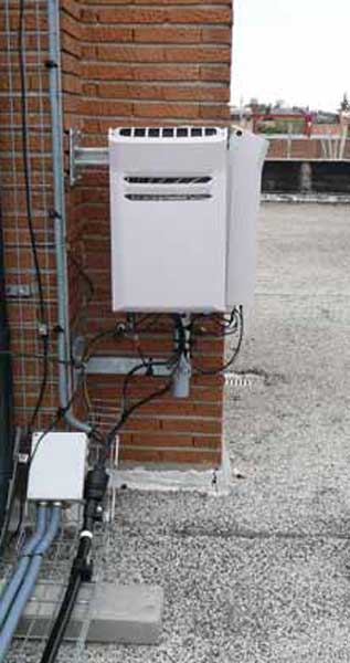
Below are
photos from Corning showing a remote antenna head end and
antenna and the fiber terminal serving the antennas. Note
the use of a prefab cable system at the top of the tower,
making installation much easier. Some installations use a
composite cable that includes both fiber and power
conductors so only one cable need be installed up the
tower.
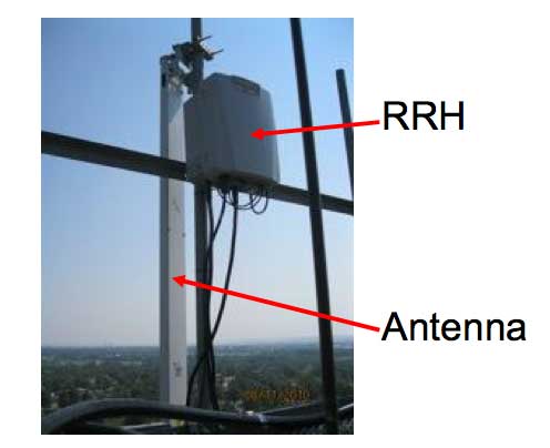
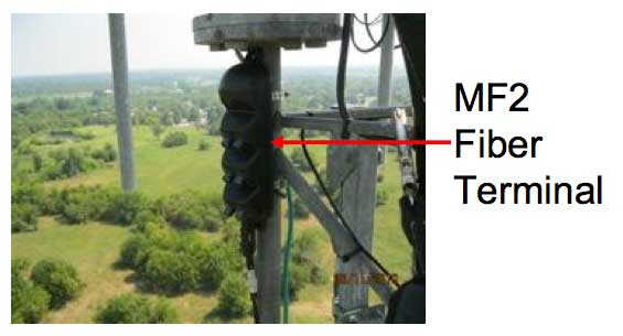
Photos courtesy of Corning.
Many cell
towers are independently owned and space for antennas is
rented to the service providers. Installation of fiber to
the towers and fiber up to the antennas is generally done
by independent contractors who specialize in this kind of
work.
Another Option - Small
Cells
Small cells go by
many names including micro-cells. They are small
integrated radios and antennas intended for small
geographic areas. They can cover the range of 700MHz to
2.6GHz with power outputs from 1-5W, much less than
regular cellular antennas. They are intended to be be
mounted on typical urban fixtures – walls, street lights,
traffic lights, bus stops, whatever gets them slightly up
off the ground.
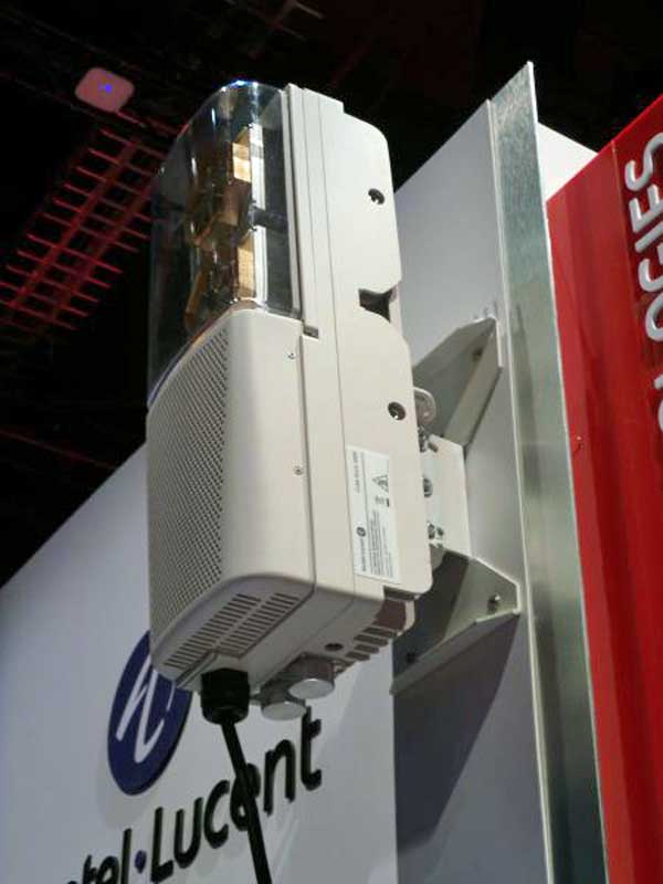
Alcatel-Lucent LightCube Radio Small Cell
Because they cover smaller areas than regular cellular
antennas, they will have fewer users connecting, spreading
out available bandwidth to increase bandwidth available
per user. Most will require only a single SM fiber and DC
power making installation easy where municipal cable
plants are available. Fiber technology for installations
is standard OSP and premises – nothing new required. We
understand they can even use PON technology to reduce the
electronics near the antenna. You can place several of
these small cells in one dome providing extended coverage
over many frequencies.
Distributed
Antenna Systems (DAS)
Distributed antenna systems (DAS) have many uses,
from providing coverage in dead zones like inside large
office buildings or campuses. They are also used in
facilities that have large crowds expecting cellular
(and wireless) services where the density of antennas is
high but the power requirements are low.
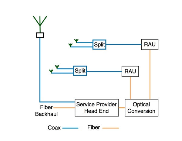
DAS diagram - typical application
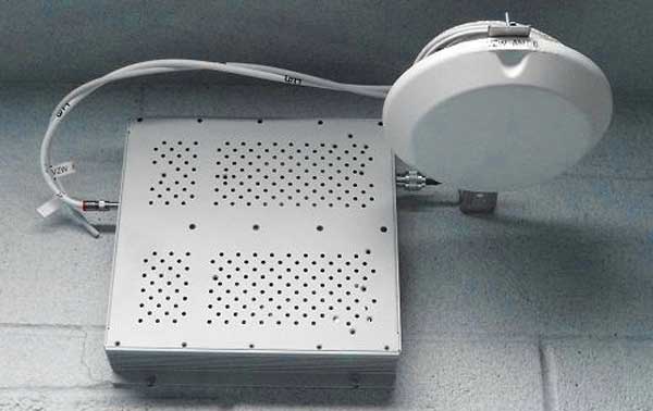
Indoor DAS Antenna and Remote Radio Unit (KLA Labs)
A DAS has to connect to service providers which is done
with fiber backhaul to all the service providers for
large facilities and may be done by wireless for smaller
facilities. Connections inside the facility will
generally be done with singlemode fiber following
standard premises cabling installation practices to the
remote antenna units (RAU) which can drive several
antennas even through coax splitters.
The block diagram here is generic – practically every
manufacturer of DAS systems has different names for the
various operational blocks and some include unique
architectures, even using PONs (passive optical
networks) like OLANs and FTTH. But the idea is to get
wireless signals to numerous remote antennas over fiber,
convert to coax at remote antenna units (RAU) and then
distribute to numerous low-power antennas, often
multiples through coax splitters, covering small areas.
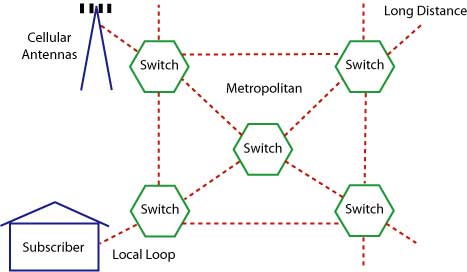
Fiber To The Tower
In a cell tower, the cellular antennas connect to users'
mobile devices, but all those communications devices must
connect into the public telephone networks. The older
towers connected on copper phone lines just like many
landline subscribers still have for their phone
connections. However older copper wires do not have
adequate bandwidth for modern mobile devices like
smartphones or tablets that consume vast amounts of
digital data.
Thus most towers are being connected on fiber that offers
virtually unlimited bandwidth. In remote areas, where
installing fiber optic cables can be expensive, microwave
links are often used. The microwave links are more cost
effective for remote towers and their limited bandwidth
compared to fiber optics may not be as big a problem since
remote towers generally have fewer users than those in
urban or suburban areas.
Connections to the cell tower
The installation of an OSP fiber optic cable is
conventional, underground, direct buried or aerial to the
tower and terminated at the base using the hardware for
the BBU. The crew doing the OSP cable install may be
different than the one doing the tower work because the
OSP crew may use different equipment and procedures than
the FTTA installation.
Connecting To Antennas
Traditional cell towers (below) use copper coax cables.
The network feed goes into a base transceiver which drives
analog signals up the tower to a masthead amplifier which
is connected by a short coax cable to a passive antenna.
Coax has high attenuation so the final antenna drive amp
is needed to provide adequate signal to drive the antenna.
The base transceiver station has interfaces for either a
digital telephone network over cable, usually fiber, or a
microwave antenna feed.
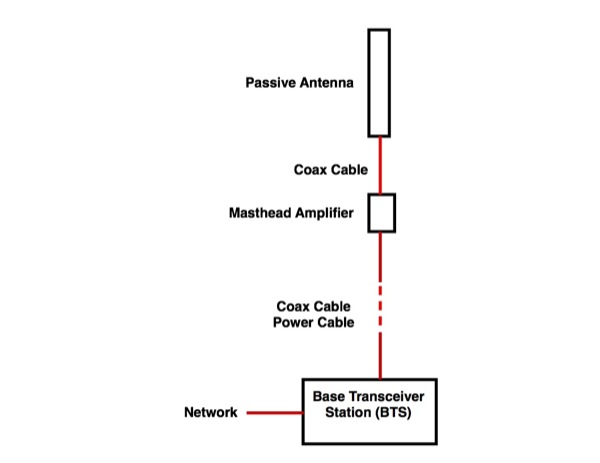
Traditional coax link to antennas
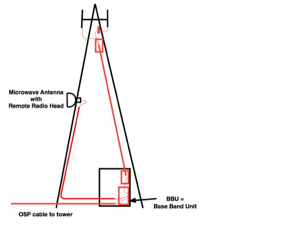
Today’s towers are moving to a digital system based on
fiber optic cable to a remote radio unit (RRU, sometimes
called RRH for remote radio head) that converts the
digital signal to analog and drives the passive antenna
over copper coax cable. Cables up the tower have fiber and
electrical conductors, usually inside an armored jacket.
The base band unit (BBU) connects to the telecom network,
either by a fiber optic cable or sometimes a microwave
antenna.
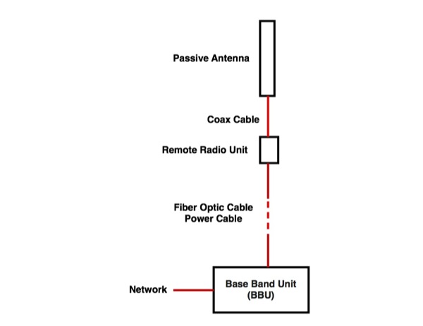
Today’s tower diagram-This is the most common system in
use now so we will focus on it.
Many systems use a digital communications standard called
CPRI - The Common Public Radio Interface –to connect the
BBU and RRU. CPRI is an industry cooperation aimed at
defining a publicly available specification for the key
internal interface of radio base stations between the
Radio Equipment Control (REC) and the Radio Equipment
(RE). The parties cooperating to define the specification
are Ericsson AB, Huawei Technologies Co. Ltd, NEC
Corporation, Alcatel-Lucent and Nokia Siemens Networks.
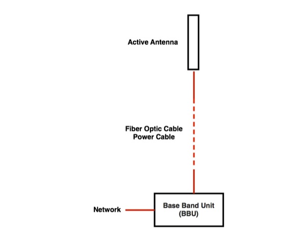
Active antenna system
Active antennas are the newest technology
and are beginning to be installed in new systems. The
antenna is an active device with the RRU integrated into
the antenna. Some towers are already being fitted with
antennas like this (2014). With an active antenna one only
needs a fiber/copper cable to bring digital signals
directly from the BBU and power the antenna.
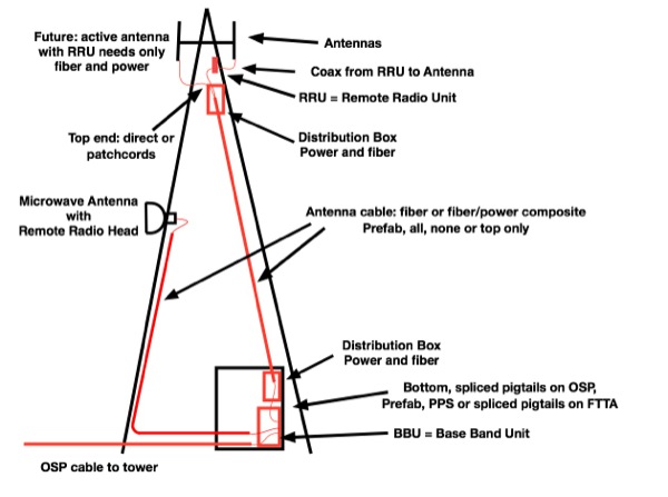
Typical Tower Diagram
Cables up the tower have fiber and electrical conductors,
usually inside an armored jacket. The top of the tower may
have a fiber/copper distribution box that connects the
RRUs. There are usually 3 RRUs for the 3 antenna systems
aimed for full wireless coverage. Some systems use one
cable to feed all 3 antennas so a distribution box is used
to break out the main cable to 3 cables for each RRU. If 3
cables are used, one for each RRU, the distribution box
may not be used. Smaller fiber-only distribution boxes are
also available. The RRUs have fiber and copper power
inputs from the BBU below and coax going out to the
antennas, either one or two cables depending on the
antenna. Various suppliers may partition the equipment at
the top of the tower differently but the functions
generally follow this diagram.
FTTA tower diagram
Cables
are often prefab assemblies, terminated in a factory to
the proper length and shipped on large spools for safe
transport. Typical
FTTA cable has both fiber and copper power conductors in
one cable, often with armor under the jacket for
protection. The fibers may be either singlemode or
multimode fiber depending on the electronics. Connectors
are usually duplex LC types chosen for their small size.
The main issues for installers are to make certain the
fiber optic cables are protected and not damaged during
installation.
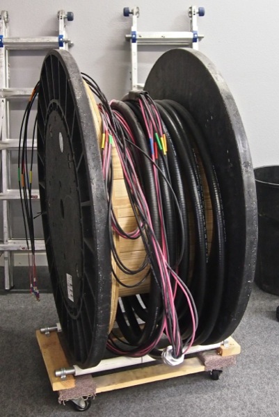
Cable on spool
This cable has 12 fibers for 6 links plus three power
conductors
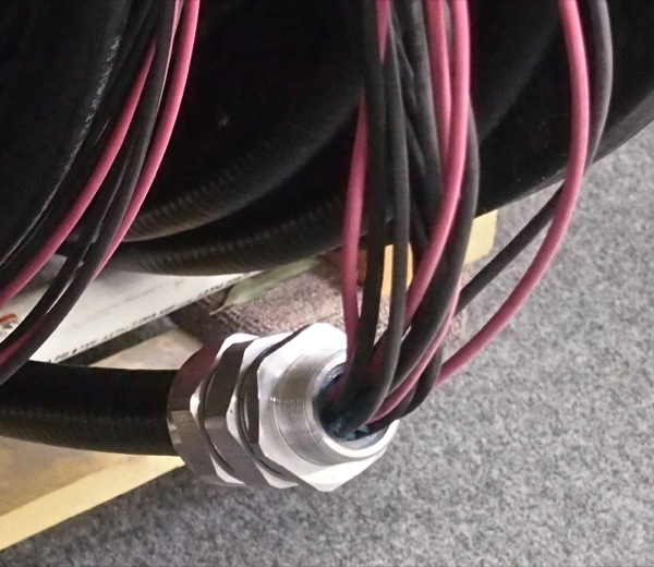
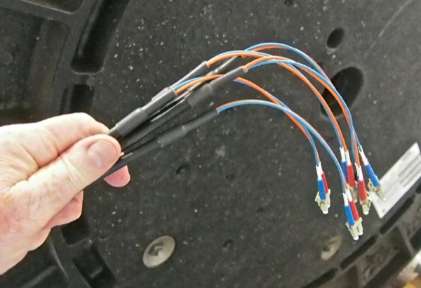
Here
you can see the individual fiber optic cables and copper
conductors exiting the cable’s armored jacket and the
rugged sealed fitting on the cable for the distribution
box. The individual cable breakouts and their duplex fiber
optic connectors should be handled carefully to prevent
damage or contamination from dirt. Some cables that plug
directly into equipment use LCs in a ruggedized sealed
housing.
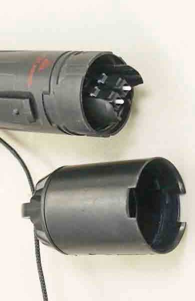
Another alternative for cabling is to use these cables
(below) with rugged outlet boxes adapted from aerial
cables used for FTTH – fiber to the home. The connections
are sealed with o-rings for reliability and mate to duplex
patchcords. This alternative is easy to install,
lightweight and rugged, but may not include the power
which must be handled separately.
FTTA cables may have either multimode (MM) or singlemode
(SM) fiber depending on the fiber requirements of the
BBU/RRU units specified. MM fiber has a larger core than
SM so is somewhat more forgiving for cleanliness but both
must be handled carefully and and cleaned thoroughly
before use.
Installing Cables
As you can see from the cable on the spool above, these
cables are not lightweight, especially since they must be
pulled up to the top of cell towers which may be as high
as 300 feet (100m.) A crane or winch is needed to raise
the cable to the top and hold it while it is secured. In
this photo (provided by Corning) the cable is being
winched up along with a bucket holding the accessories
needed to secure and connect it.
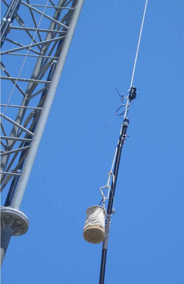
Pulling cable up the tower (Corning photo)
Installers must use a winch or crane to get the cable up
the tower. If the cable is armored, a kellum’s grip can be
used to hold it, or a pulling loop may be provided. The
cable is secured to the tower with appropriate fasteners.
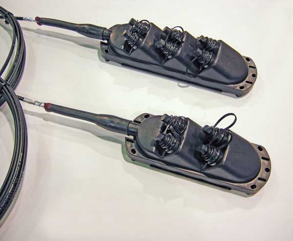
Tower Hardware
Below
is an example of the equipment for a tower as used in
the training lab of Wireless Workforce (http://thewirelessworkforce.com).
The top distribution box has a patch panel for the fiber
to break out to three RRUs. It also includes a copper
breakout with lightning surge protection. The lower
distribution box also handles both fiber and copper
connections but is bigger to allow for storage for
excess cable. If the cable is too long, the corrugated
jacket can be stripped and the excess fiber stored in
the box. Copper conductors can be cut to length. The
distribution boxes also have provision for grounding and
bonding the corrugated metal armor of the cable.
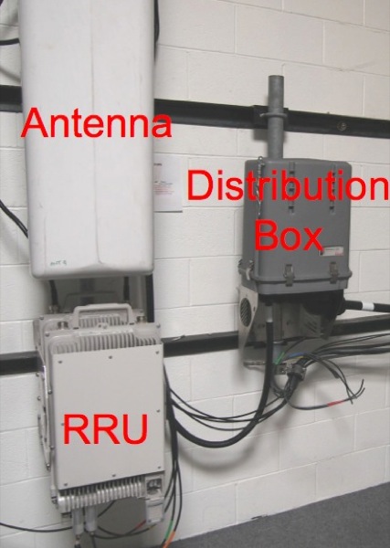
Equipment at the top of the tower
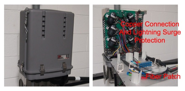
The top distribution box has a small fiber patch panel
to connect patchcords from the RRU to the cable coming
up the tower. It also has power connections for the
equipment and lighting surge protectors.
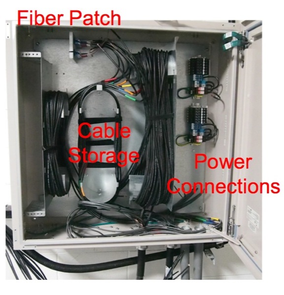
At the bottom of the tower, another distribution box
handles both fiber and copper power connections and
provides storage for excess fiber optic cable.
Patchcords connect from here to the BBU.
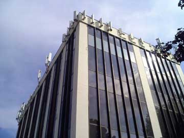
Rooftop Installations
Rooftop installations require permission from the building
owner and the installation designer will work with the
owner on the location of antennas (some do not allow
external mounting like this) and negotiate on how the RRUs
and BBUs will get installed, as well as how the fiber and
power will be routed to the equipment on the roof. It’s
not unusual to install cable trays or conduit for the
cables on the roof to keep them organized and make them
look more attractive.
Antennas on building
Note the different types of mountings on the antennas on
this building, likely from different carriers on the same
building.
Rooftop installation (RFS Hybriflex)
It’s hard to generalize about rooftop installations as it
depends on the building structure, location of the
entrance facility in the building and number of service
providers using the building. Most buildings will have the
BBU somewhere downstairs in the building near the entrance
facility for service providers and fiber running to the
RRUs and antennas on the roof. Buildings must have space
for entrance facilities, electrical services and cabling
for the systems. Some building may mount the antennas on
the building, some may have towers on the roof built for
the antennas. Cables run in the building will probably
have conduits or cable trays for managing all the
necessary cables. Most issues will be negotiated with the
building owners and managers.
Small Cells
Small cells go by many names including microcells. They
are small integrated radios and antennas intended for
small geographic areas. They can cover the range of 700MHz
to 2.6GHz with power outputs from 1-5W, much less than
regular cellular antennas. They are intended to be be
mounted on typical urban fixtures – walls, street lights,
traffic lights, bus stops, whatever gets them slightly up
off the ground. Because they cover smaller areas than
regular cellular antennas, they will have fewer users
connecting, spreading out available bandwidth to increase
bandwidth available per user.
Two small cells in an outdoor housing
Most will require only a single SM fiber and DC power
making installation easy where fiber optic cable plants
are available. Fiber technology for installations is
standard OSP and premises – nothing new required. We
understand they can even use PON technology to reduce the
electronics near the antenna. You can place several of
these small cells in one dome providing extended coverage
over many frequencies.
Cabling Options - Prefab
Assemblies or Terminate Onsite?
Most FTTA cables will be prefabricated in a
factory for the length needed for the tower, so field
termination is not necessary. If you need to terminate
onsite (hopefully at the ground level only), there are
options with prepolished/splice connectors that produce
good results – just check the manufacturer’s
specifications to see if they are rated for the extremes
of temperatures expected in the location of the tower.
Fusion splice-on connectors or pigtails may be more
reliable for extremes of temperature.
The FOA training curriculum and Guides have information on
termination in
general and every type of fiber optic termination.
See the Table
of Contents of the FOA Guide.
Connector Handling And
Cleaning
You must never assume that factory-installed
connectors are perfect or stay clean. Certainly they
should have been perfect when made and tested at the
factory, but the factory puts protective caps on the
connectors to ship them. We call those caps “dust caps”
and, as the joke goes, they are called “dust caps”
because they are usually full of dust. So after you
receive the cables, you should first remove the dust caps
and inspect the connector ferrule end face for dust and
scratches. Then you clean them, inspect to assure yourslef
the cleaning was done properly, then test them. Likewise
before you insert them into the receptacles to mate with
another connector, give them a quick dry cleaning before
insertion.
Never touch the end of the connector because the oils on
your finger will
Dirt is the #1 enemy of fiber optic connectors because it
can cause loss and reflectance, even damage connectors.
Inspect every connector before you make a connection with
it. Check the connector and the receptacle it will be
plugged into as either or both may be dirty.
Here is more information on cleaning
and inspecting
connectors.
Testing FTTA Cables
When dealing with prefab cables, testing involves careful
cleaning and inspection with a microscope, insertion loss
testing and in some cases, OTDR testing.
Like any fiber optic cable and especially any prefab
cable, the tower cable should not be installed until it
has been tested to confirm that the cable is OK. This also
includes the patchcords used on the tower. Even short
cables can cause major problems if they have been damaged
or are not clean.
Testing includes cleaning and inspecting the connectors,
checking continuity with a visual fault locator (VFL),
then do a loss test with an optical loss test set to
determine if all fibers are OK. Recording this data will
help in the final test, after the cable has been
installed, by comparing losses before and after
installation to see if any damage was done during
installation.
Remember to always keep protective caps on all the
connectors except when cleaning, inspecting or testing.
After installation, the cable needs to be tested again to
ensure no damage was done to the cable during
installation. Insertion loss testing and perhaps OTDR
testing will be required.
More
on FTTA testing.
More On Fiber For
Wireless
FTTA- Fiber To The
Antenna
Testing FTTA
Fiber
DAS - Distributed
Antenna Systems
Small Cells
WiFi
- Premises Wireless
Comparing
WiFi, Small Cells and DAS.
FOA
Guide Table of Contents.
|