
Outside Plant Fiber Optic Cable Plant InstallationJump To: The Role of the Contractor in an InstallationAlso see OSP Construction in the FOA Guide
The Installation After the process of designing fiber optic networks is completed, the next step is to install it. What do we mean by the “installation process?” Assuming the design is completed, we’re looking at the process of physically installing and completing the network, turning the design into an operating system. This chapter covers preparing for the installation, requirements for training and safety and then the actual installation process. Since outside plant fiber optic networks can cover a broad range of installation types using varied components over different types of geography, it is impossible to cover the specifics of any one installation. This chapter should provide an overview of the various options available in OSP installations and general knowledge that should prepare those involved in any particular installation to understand how to proceed. The Role of the Contractor in an Installation To begin work on a fiber optic installation, the network owner or user must choose a contractor, perhaps the most important decision in the entire process. The fiber optic contractor should be able to work with the customer in each installation project through six stages: design, installation, testing, troubleshooting, documentation and restoration. The contractor must be experienced in fiber optic installations of the type involved and should be able to provide references for similar work. One should be able to rely the contractor to not only do the installation but to assist in the design of the network and help choose components and vendors. Once the contractor has been given the assignment, they should be able to help the customer with the design, including choosing the right kinds of fibers, cables, connectors and hardware for the installation. The contractor should know which components meet industry standards to ensure interoperability and what state of the art components will facilitate future expandability. The experienced contractor also should be able to help in the choice of vendors. Experience with particular product types and vendors will allow the contractor to assist the customer to choose products that make the installation faster and easier and often higher performance and more reliable. Should the customer choose components that are unfamiliar to the contractor, it is important that the contractor know early in the process so they may obtain proper training, often from the manufacturer, as well as any unique tools that may be required. Generally, the customer is not as familiar with fiber optic technology and practice as an experienced contractor. The contractor may need to discuss certain choices with the customer where they believe alternatives may be better choices. The actual installation process can involve more than just putting in cable, terminating and testing it. If the contractor is knowledgeable and experienced, the user may ask the contractor to purchase, receive, inspect and bring components to the work site also, which can be another good source of revenue for the contractor. Having full control of the materials process can also make life easier for the contractor, as they have a better chance to keep on schedule rather than depending on a customer who has many other priorities. Plus, they may have the latitude to choose components they are more familiar with, facilitating the actual installation process. The technicians actually doing the installation should be trained and certified by organizations like The Fiber Optic Association (www.thefoa.org) and/or manufacturers of the products being installed. Certification provides a level of confidence that the installation techs are knowledgeable and have the skills needed for the work involved. The final four requirements from the contractor, testing, troubleshooting, documentation and restoration, need to be discussed before the project ever begins. Every fiber optic project requires insertion loss testing of every link with a light source and power meter or optical loss test set according to industry standards. Some projects, like long outside plant links with splices, may also require OTDR testing. The contractor and customer must agree that testing includes troubleshooting problems and fixing them as well as documenting test results for every link. Likewise, for the contractor, documentation must begin before the project starts so the scope of work is known to everyone and end only when the final test data is entered. Copies of the documentation, along with excess components left over from the installation, must be presented to the customer to facilitate future network restoration, should it be required. The Contract The contract for a fiber optic installation should include detailed requirements for the project, spelling out exactly what is to be installed, acceptable test results, and documentation to be provided. All this should be discussed between the customer and the contractor and agreed to in writing. They are not irrelevant details, as they are important to ensure the customer gets what they expect and the contractor knows what is expected of them when designing the network, estimating costs, doing the actual installation and providing proof of performance in order to show the work is completed and payment should be made. Planning For The Project Once the contracts are signed and a set of plans has been handed to the contractor, what’s next? Planning the job is the first task. Proper planning is important to ensure the job is installed properly, on time and meets cost objectives, so the contractor can make a profit. It is assumed you have a finished design for the project, know where and how everything will be installed and have any special requirements like permits ready. One can also assume you have a completion date, hopefully a reasonable one, to work toward. The first step then is to create a schedule which will be the centerpiece of the planning process. In order to schedule a job, you need a lot of information, much of which can be acquired from estimates you did when bidding the job. When buyers price the components to be used on a job, they should get delivery times as well as prices. Some items used on fiber optic projects should be stock items, like connectors, patch panels or splice closures. Cables, however, may have to be made to order. Many fiber optic cables are custom items, depending on the cable type, number and types of fibers and color coding. Custom cables will often be less expensive because they don’t have extra fibers for specifications you don’t need, for example, but they will have longer lead times since they must be made from scratch. Whenever specifying a fiber optic cable, always try to have a few extra fibers available, just in case fibers are damaged during installation. The astute contractor tries to always use the same types of components on every job so they are familiar with not only the installation procedures but the typical costs, yield (i.e. number of connectors or splices that will pass testing first time) and any problems likely to be encountered. If any components are not familiar to the installers, they need to learn how to install them correctly, either by experimenting in the office on off-time or getting manufacturers to train them. The need for training may also arise if new equipment types are required, such as outside plant cable placing tools or new types of test equipment. The cardinal rule of installation is never take an unfamiliar component or tool on the job; it’s a recipe for disaster. Buyers need to order the components when the job is acquired, scheduling delivery to the job site either to have everything available before the installation begins, or on a large job with an extended schedule, according to how long the installation of that component will take. Here you also need to plan on where the components will be delivered to, either a staging area in your warehouse, for example, or to the job site. Components delivered to the job site may require security. Theft can be a problem with cable particularly, since many thieves think all cables contain copper and the price of copper makes cable worth stealing. But vandalism is another concern, requiring components be either locked up or if too large to put indoors like large spools of cable or fiber optic innerduct, may require on site overnight guards. Next, one needs to schedule labor. Again, the estimates should tell you how many installers of what experience will be needed and how long they are expected to need to complete the installation. If any training is needed, additional time may need to be added to the schedule. Having covered labor and materials in the schedule, the planning is almost done. Review the schedule with everyone involved to get them on board and start the processes, beginning with acquiring materials. Then add to the plan a review of safety rules for supervisors, installers and anyone expected to be on site. Also add notes to keep all scrap cable, connectors, etc. to package and present to the user in case they are needed for future restoration. If the start date is not tomorrow (because the customer wanted it yesterday!) and you have other projects in the interim, pull out this schedule regularly to check if everything is on schedule to prevent any last minute surprises. Installation Checklist Planning for the installation is a critical phase of any project as it involves coordinating activities of many people and companies. The best way to keep everything straight is to develop a checklist based on the design. The checklist below is comprehensive but each project will have some of its own unique requirements that need to be added to the list. Pre-install checklist: Main point of contact/project manager chosen Link communications requirements set Equipment and component requirements set and vendors chosen Link route chosen, permits obtained Cable plant components and vendors chosen Coordination with facilities and electrical personnel complete Documentation completed and ready for installation, preliminary restoration plans ready Test plan complete Schedule and start date set for installation, all parties notified Components ordered and delivery date set, plans made for receiving materials (time, place,) arrange security if left outside or on construction site Contractor/installer chosen and start date set Link route tour with contractor(s) Construction plans reviewed with contractor(s) Components chosen reviewed with contractor(s) Schedule reviewed with contractor(s) Safety rules reviewed with contractor(s) Excess materials being kept for restoration reviewed with contractor(s) Test plan reviewed with contractor(s) Before starting the install: All permits available for inspection Sites prepared, power available All components on site, inspected, 24-hour security arranged if necessary Contractor available Relevant personnel notified Safety rules posted on the job site(s) and reviewed with all supervisors and installation personnel During The Installation: Inspect workmanship at every step Daily review of process, progress, test data Immediate notification and solution of problems, shortages, etc. After completion of cable plant installation: Inspect workmanship Review test data on cable plant Set up and test communications system Update and complete documentation Update and complete restoration plan Store restoration plan, documentation, components, etc. Preparing For Outside Plant Installations Outside plant (OSP) installations of fiber optic cables can be much more diverse than premises installations. OSP installs may include installing aerial cable, direct-buried cable, underground cable in conduit or installing conduit or innerduct and then pulling cable, or placing cable underwater. A single link may include several types of installation, for example aerial in one section, pulling in conduit on a bridge crossing and burying the rest of the cable. Cables may end when pulled into buildings or terminated at the top of poles where surveillance cameras or wireless access points are located. Splices where cables are concatenated can be placed in pedestals, buried underground or hung in aerial splice closures. The diversity of OSP installation makes it extremely important for the contractor to know the route of the cable to be installed intimately. Like the estimator who should walk the route before beginning the estimating process, the contractor needs to see for themselves the actual situations they are going to encounter. That inspection allows them to determine what problems may be encountered, what special equipment may be needed and even double check that all the permits needed are in order. Long cable pulls in conduit may require lubricants or intermediate pulls where your installers need to know how to “figure 8” cable to prevent kinking, a procedure described later in this chapter. Call Before You Dig 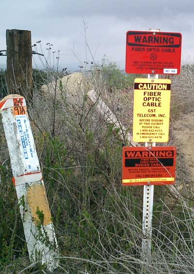
The old story about the most likely fiber optic communications system failure being caused by "backhoe fade" is not a joke – it happens every day. But it reminds us that digging safely is vitally important. The risk is not just interrupting communications, but the life-threatening risk of digging up high voltage cables or gas lines. There are several services that maintain databases of the location of underground services that must be contacted before any digging occurs, but mapping these should be done during the design phase and double-checked before digging to ensure having the latest data. At the same time as the cable is installed, markers like these indicating its location and ownership can also be installed. More on OSP construction (underground and aerial) Pulling and Placing OSP Cable OSP installations fall into four broad categories, underground, direct buried, aerial and submarine (or underwater.) Each used different procedures, tools and even cables. Underground Cables 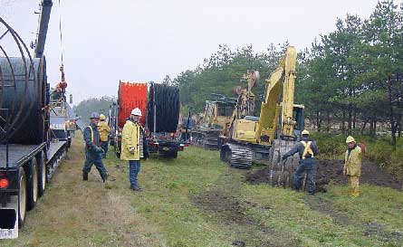
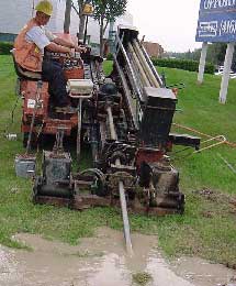
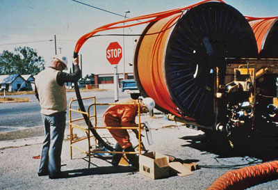 Digging trenches to bury fiber optic duct and pulling cables into duct Underground cables are pulled in conduit that is buried underground, usually 3-4 feet (1-1.2 meters) deep to reduce the likelihood of accidentally being dug up. The process usually begins with digging a trench to bury the conduit which is generally 4 inch plastic pipe, sometimes with pre-installed innerduct (also called duct liner) with a pulling tape to facilitate the actual cable pulling process. Directional boring can also be used to avoid digging up the surface, for example in crossing streets or sidewalks. If the conduit and cables are all dielectric, a conductive marker tape may be buried about a foot above the conduit to assist in future cable location and as a warning to anyone digging in the vicinity of the cable. Due to the disruptive nature of burying conduit, especially under roadways, many governments which grant permits for burying cable require the contractor to install extra conduits along the route to prevent having to dig again for any future cable installations. Since many cities have extensive conduits already buried for other services or may have required extra conduit to be buried during prior installations, conduit may be available for pulling new fiber optic cables. Innerduct inside the conduit separates the cables and provides easier pulling of cables. Conduit can be purchased with innerducts installed, generally with pulling tapes also. If the innerduct does not have a pulling tape installed, a line may be blown through the duct to pull a stronger pulling tape or line through the duct. Unless innerducts are installed in a conduit, only one cable can be installed in the conduit unless all the cables are pulled together. Pulling a cable into a conduit which already has several cables may cause tangling, increasing pulling tension and potentially damaging cables. Multiple cables may be pulled at once if the total cable fill and pulling tension does not exceed recommendations. Innerduct or duct liners come in several types, including flexible tubes with corrugated or smooth interiors. Corrugated tubes with smooth liners have a greater tendency to flatten, limiting cable size, while corrugated interiors may be more fragile. A new type of duct liner is more like a fabric sleeve that lies flat until the cable is pulled through it, and takes up less space in the cable than rigid innerduct allowing space for more cables. The length of cable that can be pulled will depend on many factors, including the type of cable, conduit or innerduct, temperature, and straightness of the run that affect the coefficient of friction. Except for short pulls, cables should be lubricated to reduce friction that increases pulling tension. Lubricants should be of a type approved by the cable manufacturer, not lubricants for copper communication or electrical cables, and applied per the lubricant and/or cable manufacturer. Some lubricant manufacturers offer online calculators that will help in choosing and using lubricants. Most cables can only be safely pulled by attachment of a swivel pulling eye to the strength members of the cable. Swivels are important to reduce twisting loads on the cable. For high tension loads, a breakaway swivel is used to prevent damage if pulling tension exceeds the cable specification. Some cables are rated for pulling by the jacket if a flexible wire mesh grip, commonly called a Kellems Grip, is used. These are also usually attached to the strength members of the cable. Later in this chapter are instructions for attaching pulling eyes. Tension for pulling cables is often high enough that a powered capstan will be needed, probably for all but the shortest pulls. The capstan should be equipped with a monitor that can shut down pulling if a preset tension is exceeded. If tension becomes too high, the cause of excess friction needs to be found and fixed. As with any cable installation, it is important to not bend the cable too tightly which may cause damage to the cable or its fibers. Standard cable guidelines are a minimal bend radius of 20 times the cable diameter under tension and 10 times the cable diameter after the pulling tension is removed. After pulling the cable may still have some tension at points, but if properly lubricated and carefully pulled, it should be minimal. Cables can be pulled completely from one end if the length is short enough and there are no intermediate locations like manholes or vaults where the cable is to be pulled through, not spliced at that location. Devices exist to assist at midspan allowing pulling out of one conduit and into another at some locations, or the cable may be pulled to the location, laid on the ground in a figure 8 pattern to prevent twisting and then pulled through the next section. Alternately, cable can be pulled in one direction from an intermediate point, the remaining cable unspoiled in a figure 8 pattern, the flipped and pulled in the other direction. See the section on figure 8 cable pulls later in this chapter. Cables can sometimes be installed by blowing special cable types into ducts called duct lines, micro-ducts or sub-ducts which have been installed in larger conduit or even pipes for carrying water, sewage or gas. High pressure compressed air provides an aerodynamic effect, floating the cable on the air stream and carrying it down the duct, allowing installation lengths as long as 2 km (6,500 feet.) At any cable ends where splicing or termination is required, an extra 30-60 feet (10-20 meters) of cable should be left for splicing. Most splicing will be done in a trailer or tent on the ground and extra cable is needed to reach the splice location and have extra length to strip for splicing. Before beginning installation, check splice closure instructions for cable lengths required for splicing or midspan entry. Always allow extra length to cut off the pulling eye from the pulling end. As with any cabling installation, work should be done in a neat and workmanlike manner. Cables should be neatly lashed in the proper locations in manholes or vaults, using cable ties but never tighten cable ties tightly as that can cause problems with the cable or fibers. Service loops should also be neatly lashed in place. At intermediate locations, it is extremely important to place identification tags on fiber optic cables to allow easy identification and prevent damage in the future if the cable is mistaken for a cable that is to be cut and removed. Cables terminated inside premises need to be neatly installed. Conduit or cable trays should be used to protect the cables. Most building, fire or electrical codes limit the length of OSP cable that can be run indoors unless the cable is in conduit, so proper cable installation includes meeting appropriate building codes. Buried Cables 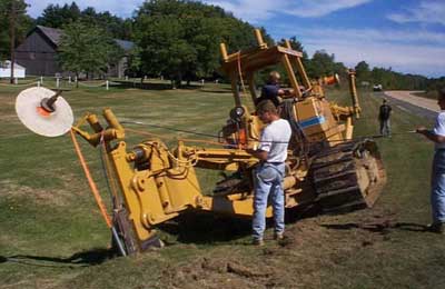
 Plowing in d irect buried cables (L) and directional boring (R) If the geography allows, fiber optic cables of the appropriate types can be buried directly in the ground by plowing directly into the ground, directional boring or trenching and placing the cable in the trench. Where the ground is soft and relatively free of rocks and the land is flat and has no obstacles for the movement of heavy equipment, direct burial is a fast method of installation, allowing several miles/km of cables to be installed in a day. In more built-up areas, trenching may be easier because plowing requires big machinery and lots of room. Heavy-duty cables can be buried directly or cables in ducts for extra protection can be installed using direct burial techniques. Cables can be supplied already in ducts for burial. An alternative technique is to bury duct and blow cables into the ducts as is done in underground installations. Typically trunk cables in most areas are installed 3-4 feet deep (1-1.2 m), but in residential or urban areas, cables may be buried only 2 feet (0.6 m) deep. Some cables can be directly installed in sawn grooves in roads, but these are only buried a few inches deep, still within the roadway material and are filled with sealer. If the cable is all dielectric, a conductive marker tape may be buried about a foot above the conduit to assist in future cable location and as a warning to anyone digging in the vicinity of the cable. Plowing cables can be done with large static plows or smaller vibratory plows, but they should be plows rated for pulling fiber optic cables. Plows for copper cables may not meet fiber requirements for cable support, bend radius, tension or vibration. Sometimes the cable plowing is proceeded by a ripping operation where a preliminary plowing is done to prepare the ground and find underground obstacles. Plowing in cable requires careful feeding of the cable into the cable chute of the plow to reduce stress. A capstan feed is used on many plows to synchronize cable feed. The cable reel and feed chute should be isolated from vibration also. Plowing in fiber optic cables is a process that demands care and experience. Needless to say the plow operator and crew need to know what they are doing and exercise great caution. Inexperienced personnel should work with an experienced crew to learn the proper procedures. Trenching involves digging a trench with a backhoe or trencher, laying the cable and then filling the trench. All sizes of trenchers are available, and don’t need to be fiber specific equipment unlike plows. The contractor needs to be careful about sharp objects or rocks in the trench or filler since they may damage the cable. If the ground is rocky, burying the cable in sand before filling the trench will provide protection.  Microtrenching is another method used for underground installation, generally on roadways or in private yards for fiber to the home connections. Microtrenching involves digging a narrow and shallow trench about 25mm (1 inch) wide and 200-250mm (8-10 inches) deep using a special tool. Tools are available that can cut through asphalt or concrete roadways or sidewalks or for cutting in bare ground. After cutting the trench, one can install a special cable or microducts in which cables can be installed by blowing. A typical trench can accommodate a microduct with up to six ducts providing for future expansion. Blown cable installation refers to a method of installing small cables in microducts using compressed air and a machine that pushes the cable into the duct. The cables are not really blown into the duct, but the blowing air floats the cable in the duct and reduces friction so the machine can push the cable into the duct. This method works well in both OSP installation, often with microtrenching to install the ducts, or in premises installations where the duct is installed first and the the cable is blown in. With today's microcables, it's easy to install high fiber count cables this way since a typical 144 fiber cable is only 8 mm (0.3 inch) diameter. One can even install special ducts that allow blowing in fibers only, not cables, although that not as popular. Cables may also be buried by directional boring, a method often preferred when crossing roads or shallow waterways as it does not require digging up the surface. The size and length of the bore are related, as bigger bores can not be made over as long a length, and both may be determined by the type of ground encountered. Directional boring also requires exact knowledge of other buried utilities to prevent damage to them during the boring process. Buried cables may be spliced in closures which are buried along the cable route or placed above ground in a pedestal. At any cable ends where splicing or termination is required, an adequate length of cable must be left, typically an extra 30-60 feet (10-20 meters) of cable for splicing in a trailer or tent on the ground. Before beginning installation, check splice closure instructions for cable lengths required for splicing or midspan entry. Always allow extra length to cut off the pulling eye from the pulling end. As with any cabling installation, work should be done in a neat and workmanlike manner. Cables should be neatly lashed in the proper locations in manholes or vaults, using cable ties but never tighten cable ties tightly as that can cause problems with the cable or fibers. Service loops should also be neatly lashed in place. At intermediate locations, it is extremely important to place identification tags on fiber optic cables to allow easy identification and prevent damage in the future if the cable is mistaken for a cable that is to be cut and removed. Cables terminated inside premises need to be neatly installed. Conduit or cable trays should be used to protect the cables. Most building, fire or electrical codes limit the length of OSP cable that can be run indoors unless the cable is in conduit, so proper cable installation includes meeting appropriate building codes. Aerial Cables 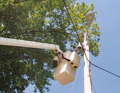
 Installing aerial cable to CCTV camera (L), OPGW spliced to underground fiber optic cable In many areas, cables are still installed on utility poles. Aerial cables are subject to continual tension as well as extra tension caused by temperature changes, wind and in some areas, the weight of ice. Most fiber optic cables do not have sufficient strength to allow direct aerial installation, but there are methods to install them aerially as well as special cables that are designed for aerial installation. The simplest solution is to lash a regular OSP cable to a messenger, usually a metallic stranded cable used to support the cable but sometimes another cable if it has adequate strength. CATV overbuilds sometimes lash fiber cables to existing coax cables and even power cables can have fiber optic cables lashed to them. The messenger must be selected to have adequate strength to support the fiber optic cable over the span between support structures. Care must be taken when installing fiber optic cables with a messenger to accommodate length variations in the messenger, for example due to stretching in the wind or with temperature changes. Since optical fiber cables are designed not to stretch as that would stress the optical fibers, slack must be provided, usually at the supports, to reduce tension on the fiber optic cable when the messenger length changes. The National Electrical Safety Code and RUS provide guidelines for support structure design, but manufacturers should always be consulted about the proper support methods for the cables being chosen for aerial installation. The first stage of a lashed aerial installation is installation of the support messenger cable. Typically the strand will be laid on the ground along the span, pulled onto the poles using pulleys, then have the tension adjusted and the messenger clamped securely. Lashing of the optical fiber cable to the messenger must be done separately on each span of the cable installation. The optical fiber cable can be pulled onto temporary support rings and lashed, or alternately, laid along the ground under the messenger and an aerial guide in front of the lasher used to position the cable next to the messenger for lashing. Some methods also use a truck that pays out the cable and pulls the lasher. Cables with built in messengers, called figure 8 cables (not to be confused with the process of coiling cables on the ground called “figure 8-ing”,) can be installed directly as the support structure is built into the cable. The cable is supported by clamping to the strength member of the cable in a manner similar to installing a messenger strand. One can also buy aerial conduit, a small fiber conduit with a messenger attached like a figure 8 cable and then an OSP fiber optic cable can be pulled into the conduit. There is also a category of all dielectric self-supporting (ADSS) cables that are designed with more strength members and a thicker jacket to have adequate strength to withstand the rigors of aerial installation when installed with special hardware designed to grip the cable on the jacket properly without causing damage to the cable over long term high tension loading. As each manufacturer generally has their own hardware and procedures, they should be consulted during the design stage for proper cable plant design and placement procedures. ADSS cables have two types of mounts, ends or dead-ends where the cable is supported against the tension caused by the installed cable, and pass-throughs where the cable can be attached to a pole but allowed to move within the assembly. Ends don’t mean the end of the fiber optic cable, but a location where the cable is held firmly under tension. At a pole, two ends may be used to change directions of a cable, provide slack for tensioning or to allow ends to be brought to the ground for splicing. Tensioning can be done with a chain hoist with gage to set tension. Another type of aerial cable is optical power ground wire (OPGW.) OPGW is a high voltage conductor with a hermetically sealed tube in the center which contains optical fibers. This cable is widely used throughout the world to provide communications as well as power. OPGW is installed in the same manner as high voltage cable but ends are brought to the ground and spliced or terminated, the coiled up on the tower. If communications equipment is required at that location, fiber optic cables are brought from the splices into a local facility housing the equipment. Installation of OPGW should be left to experienced utility personnel except for splicing which may be done by fiber installation personnel. With all aerial cable installations where splicing or termination is required, an extra 30-60 feet (10-20 meters) of cable should be left for splicing. Even more may be required if splicing is done on the ground on cable installed on tall poles. Whenever installing aerial cabling, careful planning is very important. Working high above the ground can be dangerous and working on poles may mean working in proximity to electrical power lines. If at all possible, have the power cables shut down before installing any other cables on utility poles. Be especially careful when installing metallic support hardware for fiber cables; the fiber cables may not be conductive but the hardware can be. Install the longest cables you can to reduce the number of locations for splicing. Have proper equipment and adequate numbers of properly trained personnel on the job site, and, if possible, local authorities who may have responsibility for the installation on their property. Alternative Installation Methods Installing cables sometimes requires some creativity. Microtrenching Digging up roadways to install cables has been used in the past but often leads to complaints about the condition of the road once the cable has been installed. Microtrenching saws a groove in the pavement and drops in special cables and or ducts. The groove is refilled, often with the same material vacuumed up when the sawing occurs, making for a simple, neat installation. The process is much faster than trenching too.  Cables in Sewers This method was developed early in the history of fiber optics. Sewers and storm drains have air spaces at the top of the pipe to facilitate flow. Small remote controlled robot vehicles like the one below are sent down the pipe to install special cable trays at the top of the pipes to carry the fiber optic cables. In large pipes, the vehicles are big enough that techs can ride them and do the installations. Like microtrenching, it reduces the problems of installing cables in urban areas. 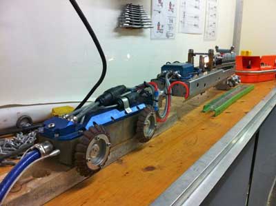 Submarine/Underwater Cabling Fiber optic cables sometimes need to be installed underwater. The best known of these installations are probably the transoceanic cables that provide worldwide telecom and Internet communications. Installing those cables is a very specialized process that requires special cable designs and custom cable-laying ships to pay out the cable over thousands of kilometer runs and place it on the ocean floor at great depths. Those applications, while interesting, are beyond the scope of this book. Other underwater installations involve river or lake crossings where it is more cost effective to lay fiber cable under water than detour around the water, place the cable in conduit lashed to bridges or other structures or run the cable aerially. Underwater crossings may require special permits because of the jurisdiction of various environmental groups. 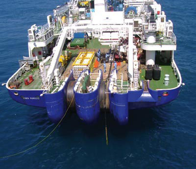
When cables are run underwater, there is always danger of the cable being snagged. For relatively shallow water, the cable should, if at all possible, be buried several feet under the bottom of the river or lake. For deeper water, special armored cables with one of more layers of wire armor should be used to prevent damage to the cable if snagged. Due to the specialized splice housings needed for underwater cables, running a single length across the water will be much easier and less costly. Underwater installation brings its own safety hazards also. Experienced divers may be needed to assist in placing the cable and troubleshooting problems. Hardware and Equipment 
OSP installations may require installation of supporting structures before the cable installation can begin. New conduit or innerduct may need to be buried or conduit already in place may need to be checked, old cables removed and new innerduct installed. Some buried cables may even require the installation of pedestals, manholes or controlled-environment vaults for equipment as well as conduit. Not only does the contractor need to consider all the hardware that may need to be installed, but they have to schedule the specialized equipment needed: trenchers or cable plows, backhoes, bucket trucks, cable winches, etc. and ensure that personnel are well-trained in their use. Splicing Cables 
Once the infrastructure is in place and the cable placed, the fiber optic splicing work begins. Now scheduling the availability of appropriate fiber optic equipment is the concern. If the cable is to be spliced outdoors, a splice trailer is normally used, unless splices are being made on a pole or in a bucket, where a tent may be required in bad weather. The cable needs to be prepared for the splicing process. This involves processes appropriate to the cable type being installed, but usually includes removing the cable jacket, exposing proper lengths of buffer tubes to connect to splice trays, cutting back strength members to attach to the splice closure and cleaning all water-blocking gel or powder. Finally, the appropriate lengths of fiber are exposed and cleaned for splicing. Care should be taken to ensure each fiber is carefully placed in the splice closure to prevent damage especially if the closure must be re-entered in the future and the closure needs to be sealed carefully to prevent long term degradation. And, as we always warn splicers, careful identification marking inside the closure makes identifying fibers much easier if a later problem requires re-entry. OSP cables are often terminated by splicing on short pigtails - terminated tight buffer cables with a factory made termination. An alternative is SOCs - splice-on connectors - where a factory made connector with a very short pigtail is fusion spliced directly on the fiber. SOCs can be done without using a splice closure when terminations are inside a patch panel. Each splice needs to be verified with an OTDR test. Testing is done preferably as each splice is made and placed in the splice tray, so to be efficient, a splicer will be on the job site and a test tech will be working at the other end of the cable with an OTDR to verify each splice. Splicing machines give an estimate of splice loss but it’s just that, and going back later, opening a splice closure and re-splicing is an expensive proposition! Midspan Entry 
It is sometimes necessary to splice large fiber count cables to smaller cables at a location other than at the end of the larger cable. Rather than cutting the cable and splicing all the fibers, a midspan entry can be used to access only the fibers required for splicing to the smaller cable(s). In order to do a midspan entry, it is necessary to know what the manufacturer of the cable recommends for procedures and have the proper tools and other hardware required by the cable construction. For midspan entry, the cable sheath, which includes the jacket and armor or other protective layers on the cable, must be removed from a length of the cable, typically about 2 meters (80 inches.) The sheath is first ring cut at the beginning and end of the section to be removed. Then at one end, the sheath is shaved off with a special tool or a utility knife to access the cable’s rip cords. The rip cords are cut at the ringing point and used to cut the sheath all the way to the ring cut on the other end of the opening. When both rip cords are used, the cable sheath can be removed in two sections. Next the strength members (aramid fibers) and binding tapes (and water-blocking tapes if the cable is a dry water-blocked design) are cut and removed. The central strength member and cable stiffener then needs to be cut, with ends left for securing to a splice closure as appropriate. Entry to individual buffer tubes to access fibers to be spliced should be done with an appropriate midspan entry tool that shaves the tube for access without damaging the fibers. Inside the tube should be found a ripcord which is used to split the tub along the length required. Then the split tube is cut off at both ends. The remaining buffer tubes can be placed in the storage section of a splice closure while the exposed fibers are spliced to other cables and stored in a splice tray. As with any splice closure, care must be taken to not damage fibers or kink buffer tubes during the process and to properly store all fibers and buffer tubes to allow reentry without harming any fibers if necessary. Termination 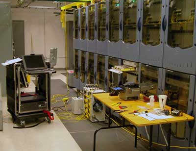
Cables will be terminated inside facilities where they will connect to communications equipment. OSP cables generally do not meet NEC flammability requirements, so the cable entering a building must be terminated or spliced to indoor cables soon after entry, generally within 50 feet (16 meters) to meet fire codes. Some OSP cables have double jackets, an outer one for outdoors and an inner one rated for indoor use, so the outer jacket can be stripped off inside the building and the cable run to the equipment room. Cables terminated in pedestals or vaults do not have this requirement. Generally singlemode OSP cables will be terminated by splicing pigtails onto each fiber and splices will be placed in a splice closure. Multimode fibers can be handled the same way or terminated directly onto the fibers. Most OSP cables will require installing a breakout kit which sleeves each fiber in a tube rugged enough for direct termination. Preparing For Premises Fiber Optic Installations Every outside plant cable project will include some premises cabling where the OSP cables are terminated, so every OSP contractor needs to be familiar with premises installation. Most building codes will require OSP cable, which is not fire-retardant, to be terminated a short distance after entering a building or be run in approved conduit. Before beginning installation of fiber optic cables and hardware in a premises installation, the site must be properly prepared for the installation of fiber optic cables, hardware and transmission equipment. During the design and planning stages, the site should have been inspected and all the hardware necessary for the cable plant included in the design. Premises Support Structures 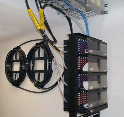
There are numerous structures used for the securing of fiber optic cable in premises installations making generalizations difficult. Cable may be hung on appropriate hangers, laid in cable trays or pulled into conduit or innerduct. Termination of the cables can be at racks in telecom rooms, in wall-mounted boxes or even wall outlets. Preparing for an install includes planning for storage of cable service loops behind racks such as shown here. You must install support structures for fiber optic cable installations before the installation of the fiber optic cable itself. These structures should follow the guidelines of appropriate standards such as TIA/EIA 569-A and NECA/BICSI 568-2001. Allow for future growth in the quantity and size of cables when determining the size of the pathways. Follow all cable bend radius requirements and avoid pulling cables around hazards if possible. Sometimes new cables can be laid in existing cable trays. Do not install a fiber optic cable in a conduit or duct that already contains cabling, regardless of the cable type to prevent damage. Existing or new empty ductwork can be modified to accept several different installations by the proper placement of innerduct. Premises support structures also include patch panels for terminations. They may be wall- or rack mounted and must be chosen appropriately for the cable types being used. Terminated simplex or zipcord cables can be terminated on open panels, but 900 micron tight-buffered fibers from distribution cables require closed termination panels for protection. If possible, the design of support structures should be such that adequate space is provided for termination of the cables and storage for service loops. Fire Stopping 
Premises cabling requires firestopping at all penetrations of walls and floors. Telecommunications firestopping must always comply with applicable codes and standards. All penetrations should be protected by type-approved firestops. In most areas the breaching of a fire separation will require physical monitoring until it has been repaired. Check with the “Authority Having Jurisdiction” for specific requirements on the project before commencing work. Electrical Systems All fiber optic equipment will require proper power at the locations of the equipment. Power must be high quality power, protected for surges and spikes, and generally must have appropriate backup capacity to prevent loss of communications during power loss. Data equipment will require a separate ground and adequate power for year-round air conditioning. Consideration should be given to efficiency in cooling to reduce power consumption. Consult with the site owner, customer and appropriate user personnel to plan electrical power installation. Grounding and Bonding 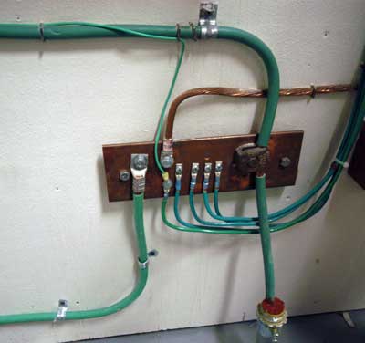
All conductive cabling and components must be grounded and bonded. Ground systems must be designed as specified by the NEC or other applicable codes and standards. Although most fiber optic cables are not conductive, any metallic hardware used in fiber optic cabling systems (such as wall-mounted termination boxes, racks, and patch panels) must be grounded. All conductive cables require proper grounding and bonding for applicable conductors. Marking and Identifying Cables Fiber optic cables should be specified with colored jackets per industry standards which identify the cables as fiber optic cables and indicate the type of fiber in the cable. All fiber optic cable terminations should be marked on racks or boxes where the cables terminate. Cables should be tagged with identification that they are fiber optic cables and proper handling is required. Particular care should be taken in premises cabling upgrades. For nearly two decades, 62.5/125 micron multimode fiber has been the primary fiber for premises cabling. With the emergence of gigabit networks, laser-optimized 50/125 fiber has become more popular. Mixing the two fibers can result in excessive loss at connections that may cause systems to not operate properly. Color coding, marking and even using incompatible connectors (SC or ST on 62.5/125 and LC on 50/125 fiber) should be used whenever possible. Removal of Abandoned Cables Unless directed by the owner or other agency that unused cables are reserved for future use and the cables are marked accordingly, it may be required to remove abandoned optical fiber cable (cable that is not terminated at equipment other than a connector and not identified for future use with a tag) as required by the National Electrical Code or local codes. At the discretion of the owner of the site, the contractor may be requested to remove other cables (e.g. copper communications or power cables) in addition. Removal of cables is much more time consuming than installation, as each cable must be identified and carefully removed to prevent damaging other cables. No cable should be cut for removal unless it is positively identified as one to be removed. All cables removed should be recycled properly. Most communications cable has significant scrap value, not only for any copper conductors but for other metallic elements and even some plastics. Equipping Installation Personnel Equipping The Installer With Tools As you near the time of the actual installation, it’s time to determine how to outfit the crews who will do the work. Choosing the proper installation and test equipment is important, as it will affect the installation time and quality or even determine the profitability of the job. The frequency of problems caused by tools is appalling: their poor design, improper use, poor condition or the unfamiliarity with their use. Installation tools include some big hardware like bucket trucks, trenchers, cable pullers or plows. The need for these will be established early in the planning stages. Many contractors do not own expensive equipment like this, finding it more cost effective to rent it as needed. If your crews are not familiar with a particular piece of equipment, subcontracting the work to someone who has both the equipment and an experienced crew may be much more cost effective, as mistakes in their operation can be disastrous – both costly and dangerous. Outside plant cables and premises singlemode cables will generally require fusion splicing for concatenation of long cable runs and splicing on pigtails for termination. Since fusion splicers have become less costly, more contractors have purchased them. Other contractors who have fewer projects that require splicing prefer to rent them, knowing they are getting a splicer that is a newer model with the latest technology that has been recently serviced. The downside of a rental unit is your installers may not be familiar with that model and require some training or time to familiarize themselves with it. If you own your splicer, it’s assumed your crews are familiar with its operation and need only to inspect the unit to ensure it’s working properly and the arc electrodes are in good condition. Most contractors own termination equipment for multimode fiber as it is used on most jobs. Generally contractors have a preferred method of termination, either adhesive/polish or prepolished/splice types. Either type requires dedicated toolkits. For epoxy or Hot Melt terminations, the appropriate curing ovens will be required, and the two are quite different; the Hot Melt oven is much hotter. If you use epoxy or anaerobic adhesives from your stock, check the expiration dates on all of them to make sure they are fresh. Also check for other consumables like wipes, isopropyl alcohol, cable gel cleaner and of course, connectors. Prepolished splice connectors have been getting better and easier to use. Newer termination kits include a quality cleaver like those used with fusion splicers and a visual fault locator to verify the internal splice. Since newer kits can now produce connectors that have lower losses, around 0.5 dB, a new kit with the latest connectors and perhaps some training could be a good investment. When checking out the termination kits, pay particular attention to the condition of the tools. Of course missing tools will need replacement, but hopefully that was done when the kits were inspected after the last job. However, tools like jacket strippers, fiber strippers and cleavers can wear out or be damaged, so its important to check their operation with some sample fibers to see if they are working properly. It’s mandatory to check out every piece of equipment you intend to take to a job site to ensure its proper operation and let the installation crew reacquaint themselves with its operation. This process needs to be done with enough time to have the unit serviced or replaced and restock any consumable supplies. It should also be obvious that one never puts back on the shelf any equipment that has had problems in the field. It should immediately be replaced or sent out for repair to be ready for the next job. Let me caution you on another problem we have seen recently with tools. Several recent complaints of poor quality tools, especially fiber strippers, have led us to believe that poor quality imports are becoming more common. In one case, the tools appear to have been counterfeit, branded with a well-known American name. I suggest you purchase tools only from reputable sources and inspect them on receipt to ensure they work properly. Finally, as the equipment is checked out and readied for use, make certain that appropriate safety equipment is packed with the tools. Everyone who works with fiber needs safety glasses and clean, unscratched ones will make seeing those hair-thin fibers much easier. Black work mats for splicing and termination also help the installer see the fibers and find fiber scraps for easier cleanup. Equipping The Installer With Test Equipment Installers also need test equipment. There are many options in the sophistication and cost of fiber optic test equipment. Proper selection can reduce both equipment costs and testing labor costs. The types and quantities of test equipment required will also vary by job type. All installation techs should all carry a visual tracer or visual fault locator. The tracer is a visible flashlight or LED source used with multimode fiber to check continuity and trace fibers to ensure proper connections. A visual fault locator is a visible laser source with higher power that can be used with either singlemode or multimode fiber for tracing, but will also allow finding some faults like stress or breaks in most simplex or zipcord cables or plain buffered fibers. Either visual tracers or fault locators are inexpensive but invaluable during the installation and troubleshooting process. Every fiber in a fiber optic cable plant requires loss testing with a light source and power meter, also called an optical loss test set (OLTS.) The OLTS will confirm that the fiber was installed and terminated properly, by testing end-to-end loss and comparing it to the loss budget created during the design phase. Big jobs may require more than one set to finish the job in a timely manner. Loss testers come in several configurations, including a separate light source and power meter usually sold as a test kit, an OLTS which is a single instrument that includes both the light source and power meter, and modules for converting copper testers to an OLTS. The individual light source and power meter are usually the cheapest solution, especially for small jobs, since the meter and source can be separated to be carried by two techs to each end of the cable being tested. If an OLTS is used, two will be needed to test a cable end-to-end, but it can test two fibers at one time, saving labor costs. The OLTS adapters for copper testers are usually not cheap, but they can take advantage of the sophisticated data handling of the expensive copper tester and produce complete reports. Contractors often choose these adapters if they have already invested in the copper testers. Each loss test set needs reference test cables. These are just good 1-2 meter long fiber optic patchcords that match the fiber size and connectors of the cables being tested. The reference cables do not have to be special cables, just ones that have been tested to have low loss. Bad patchcords will give bad test results, causing good fibers to fail testing. Reference cables need to be tested frequently to ensure they are still in good condition and have low loss. It makes good sense for each test set to have several sets of reference cables as they wear out or get damaged and need replacement. Long outside plant runs with intermediate splices will require OTDR testing. OTDRs also are good troubleshooting tools for long cable plants but are generally not designed to be used on short cables such as those common in premises applications. OTDRs are expensive, complicated instruments. Unless you use one often, it may be hard to justify the cost. Users not familiar with the quirks of interpreting OTDR data cause many problems, failing good cables and passing bad ones, often with expensive consequences. OTDRs can be rented but considering the number of problems we see caused by inexperienced users, subbing OTDR testing to an experienced contractor could also be a wise move. OTDRs need reference cables too, especially a long launch cable, sufficiently long enough to allow the OTDR to settle down from the overload caused by the test pulse. For singlemode fiber, a 1 km launch cable is recommended. 100 meters is adequate for most multimode OTDRs. New standards are calling for a cable on the other end of the cable under test to allow testing the connector on the far end, where 100 meters length is usually adequate. The most important thing to remember about test equipment is to know how to use it and always check it out before taking it to a job site. Batteries should be replaced or recharged, reference cables tested and most importantly, the user spends a few minutes refreshing their memory of how the instrument is used. On the job site is not the place to find that the equipment is not ready for use. Training and Safety Fiber Optic Training The #1 Rule Of Fiber Optic Installation is never, ever, try to install a new type of component or undertake a new type of application without proper training. Not having the knowledge or skills related to that component or application makes it virtually impossible to ensure success on the job and mistakes can be very expensive. At the FOA, we have lots of examples of installations that went wrong with terrible consequences. No one can know everything nor can any training course possibly cover all the aspects of fiber optics, all types of components and applications. Anyway, the technology is always advancing, making it important to continue gaining knowledge from all available sources. Much of the technical knowledge needed can be obtained from websites like the FOA Online Reference Guide, but what about the skills needed for working with actual fiber optic components for installation, testing, troubleshooting and restoration? Those skills can only come from training and experience. Getting More Training What kinds of training are necessary for success as a fiber optic contractor or installer and where can you obtain that training? There are many options for further training but first you need to figure out what your needs are, what training should include and who can provide appropriate training. As a general rule, all training in fiber optics that is aimed at installers must include sufficient hands-on activities with the relevant equipment, tools and components for the student to develop skills appropriate for that activity. Fiber optic techs with some experience can often learn how to install many new component types or how to operate new equipment on their own. On websites of the FOA and many manufacturers, there is tutorial information on most installation subjects as well as the FOA "virtual hands-on" tutorials (VHO) on how it's done, step-by-step. Most manufacturers have good instructions and often tutorials online to help. Given proper tools and applications information, the astute tech should be able to learn new processes in a short time. The secret, of course, is to do this in a quiet, clean office environment before trying it on a customer's site with them looking over your shoulder! Sometimes, it's better to take a course. Many FOA-approved schools offer advanced or specialist courses in termination, splicing, testing, fiber to the home, etc. that provide several days of intensive training, furnishing tools, equipment and supplies, as well as instructors who are familiar with the processes being taught. Manufacturers also offer product specific training, but one should try to get trained by applications engineers not sales personnel who may not have the depth of knowledge needed to adequately train installers. Learning to install new components There are hundreds of different types of fiber optic components that manufacturers have developed for specific applications or to simplify the job of the installer. Many of these components are unique to that manufacturer and may require special tools and installation processes. Examples are prepolished/splice connectors like the Corning Unicam, 3M HotMelt connectors, splice closures, all dielectric self-supporting cables, optical power ground wire, prefabricated cabling systems, etc. Generally, one should go directly to the manufacturer for training like this unless an independent trainer has been trained and is recommended by the manufacturer and has the proper tools and components to teach the processes required. Some manufacturers offer short introductory courses on their new products which includes limited hands-on time, and such training may be ideal for those interested in learning more about that product before committing to purchasing all the tools and components necessary to use it. Follow-on comprehensive training can be done after making those purchases. Learning to use new equipment Some of the equipment necessary for fiber optic installation is complicated and may be difficult to learn how to use without proper instruction on the same piece of equipment. Examples are automated fusion splicers, especially ribbon splicers, cable pulling or plowing equipment and OTDRs. Some of these pieces of equipment are quite complex and have peripheral products that must be used properly in conjunction with them to achieve the expected results. Ribbon splicers, for example, use ribbon strippers and cleavers, both of which are critical to achieving consistently good splices. All automated splicers have unique programming features so one needs to learn how to operate the splicer unit itself as well as how to make splices using it. OTDRs are also complicated devices and learning to use them has two parts - learning how to operate the OTDR with all its options and interpreting the data it takes in testing a fiber (the trace or signature as it is called). While all OTDR manufacturers offer "automatic testing" options, one cannot afford to trust them in all uses, as they can easily become confused by artifacts like ghosts. The user should always manually check the OTDR trace to ensure proper conclusions from test data. Training needs to be done on the actual type and model of equipment of interest, as different manufacturers’ products or different models from the same manufacturer may have unique features. To be effective, the training must include two phases - how to set up and operate the equipment itself and how to complete the processes for which it is intended. Generally manufacturers offer training on these products and independent trainers may use the same equipment or will be willing to train you on your equipment if you have already purchased it. Learning New Applications A point we make often is that there are many different applications for fiber optics and there are substantial differences in how those applications are designed, installed and tested. Outside plant techs, for example, generally terminate by splicing on factory-made pigtails, while premises techs terminate directly on fibers with adhesive/polish or prepolish/splice connectors. FTTx techs may only use prefab cable assemblies. Techs moving from one application to another may require training as well as on the job training (OJT) to understand the application and develop the appropriate skills. Finding Appropriate Training Whatever your interest, make sure the courses you take are appropriate for your interests or you'll be wasting time and money. Here are some options to consider: Can you learn it yourself? Some of us just learn better on our own. Is information on the topic readily available, for example on the FOA Online Fiber Optic Reference Guide? Good videos can help too, especially with hands-on topics like cable pulling and termination. Can you get the right tools and components to use in developing the skills necessary? Is there someone you can call for assistance? FOA's Fiber U offers free online self-study programs in many relevant topics. Does the manufacturer offer training? Does it cover what you need to know? Does it offer lots of practice with the equipment and components? Will you be certified as an approved installer for that manufacturer? That can help in getting business from customers of that manufacturer. Do independent trainers like the FOA-Approved Schools offer training in this area? Does it cover what you need to know? Does the trainer have the latest version of the equipment needed for training? Will they train you on your equipment? Is the instructor experienced and well-versed on the products and technology? Can the trainer offer manufacturer certification as well as other certifications? Where is the training being offered? Travel costs can add significantly to training costs. Remember FOA-Approved schools often offer other types of classes than just CFOT certification classes. Check with your FOA school or the online list of FOA-Approved schools for more information. Safety In Working With Optical Fiber OSP safety is a very important issue, well beyond the usual fiber issues of protecting your eyes from fiber shards or working with potentially hazardous chemicals. Routes should be cleared with “One Call” or “Call before you dig” services to ensure no buried cables or pipes are in the proposed route. Installers working with cable-placing machinery need to be well trained in how to operate them safely. Aerial installations are particularly dangerous, since poles usually have electrical cables nearby. Every OSP job should have posted safety procedures and all personnel briefed in their use. Safety in the lab or on the job site must be the number one concern of everyone. Besides the usual safety issues for construction, generally covered under OSHA rules that should be familiar to all contractors and installers, fiber optics adds concerns for eye safety, chemicals, sparks from fusion splicing, disposal of fiber shards and more. Before beginning any installation, safety rules should be posted on the classroom wall, lab wall or on the job site and reviewed with all onsite personnel. All personnel must wear the usual construction safety gear plus everyone must wear eye protection whenever working with fiber. Eye Safety Many people are concerned that the most dangerous part of fiber optic work was the chance you might get your eyes harmed by laser light in the fiber. They had confused communications fiber optics with optical fibers coupled to the output of high powered lasers used to cut metal, burn warts off skin at the doctors or perhaps they have seen too many science fiction movies. In fact, most fiber optic systems do not have sufficient power to cause harm to your eyes and the light coming out of a fiber is expanding so the farther you are away from the end of the fiber, the lower the exposure. Having said that, consider yourself warned. In more recent times, some fiber optic systems are carrying sufficient power to be dangerous and some fiber optic inspection techniques which might be used on operating systems increase the chance of harm. But that is not the biggest danger facing installers. The key to understanding the power issue is understanding power levels, wavelength of the light and the nature of light transmission in optical fiber. Fiber optic medical laser systems used for surgery and laser machining systems certainly have enough power to cause harm to your eyes, as well as burn off warts or machine some types of materials. Those systems use very high power lasers, often CO2 lasers, which emit radiation at a wavelength that is really heat not light, around 10 microns wavelength. This wavelength is readily absorbed by materials and can heat them quickly, cutting those materials easily. Fiber optic communications systems use much less power. First of all, most sources used in fiber optics are optimized for modulation speed, not absolute power. Premises cabling with multimode fiber and LED sources has very low power levels, too low to be a hazard. Higher speed premises links use VCSEL lasers, which are still quite low in power levels, and generally harmless. Most telco links use lasers with power levels slightly more than VCSELs. Two types of links have high power, as much as 100 times more than other communications systems, and they are CATV or video links at 1550 nm and telco long distance links using dense wavelength division multiplexing (DWDM.) The CATV or video links used in fiber to the home (FTTH - read more) may use fiber amplifiers (read more) that boost the power to very high levels, potentially dangerous the eye. Telco DWDM links are used on extremely long distance links (read more). They not only use fiber amplifiers for boosting the power, but they have many different signals operating at different wavelengths carried in one singlemode fiber. Any one wavelength may not be a problem, but the sum of 16, 32 or 64 individual wavelengths can be very powerful. The next issue is focusing the light from a fiber into your eye. Light exiting an optical fiber spreads out in a cone, the angle of which is determined by the transmission characteristics of the fiber as determined by the numerical aperture. As your eye gets further from the end of the fiber, the amount of radiation it receives is inversely proportional to the square of the distance; double the distance and cut the power by 1/4, ten times the distance reduces the power to about 1%. You do not have to be far away from the fiber for the power to be reduced to low, harmless levels. Because the light is exiting the fiber in a cone-shaped beam, the eye cannot focus it on the retina. This is unlike the typical lab laser or laser pointer that shines a narrow, collimated beam that does not spread out; a beam your eye can easily focus on the retina, causing temporary blindness. 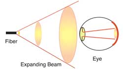
Finally, there is an issue of wavelength. Your eye cannot see many of the wavelengths used in fiber optics because the eye is sensitive to light in the blue to red region of the spectrum while fiber optic systems operate in the infrared. The liquid in your eye which is mostly water, which absorbs light in the infrared heavily. Light from most fiber optic sources will be absorbed by this liquid, so any potential harm is likely to come to the lens or cornea, not the retina. While the expanding beam of the light exiting the fiber makes it less of an issue for direct viewing, using a fiber inspection microscope can be a problem. A microscope will focus virtually all the light back into the eye. Many microscopes used in fiber optics, therefore, have filters to absorb any infrared (IR) light that could be harmful. Be wary of inexpensive microscopes which may not have IR blocking filters. To be certain fibers are safe to inspect or work with, always check fibers in an operating network with a fiber optic power meter to ensure no light is present before inspecting any connector with a microscope. Bare Fiber Safety Fiber optics installation, however, is not without risks. The more common problem is getting scraps of fiber in your eye when working with fiber. While few fiber optic systems have harmful levels of power, every termination and splice produces shards (scraps) of optical fiber which is potentially very harmful to your eyes and skin or may stick in your clothing and be carried to other locations where it may be harmful to others. These shards of fiber are tiny, thin and often very sharp where they broke off the fiber. They can easily puncture your skin, burying themselves deep enough to be difficult to pull out, if only you could see them. Being transparent they practically disappear once embedded in your skin. In most parts of your body, they merely become a nuisance, perhaps infecting or causing an irritating bump, until they eventually work themselves out. Around your eye, however, they can be much more difficult to find and remove. The tears that wet your eyes make the transparent glass shards practically impossible to find and remove. The sharp ends of the fiber may cause it to embed itself in the eye or surrounding tissue, making it even more difficult to remove. Unlike metallic particles, they cannot be removed with magnets, It is imperative to follow procedures that minimize the dangers to the eye. Always wear protective eyewear with side shields, even if you normally wear glasses, to prevent any flying shards from getting near your eyes. Be extremely careful whenever handling fibers, especially when stripping fiber or scribing and breaking fiber extending out of an adhesive connector. Instead of breaking it, scribe it gently, then slide your fingers up the connector ferrule, grasping the fiber and pulling it off. Then dispose of it carefully. Most cleavers used for splicing or terminating prepolished/splice connectors hold the fiber after cleaving, so the only problem is disposing of it. We recommend using disposable containers like those used for soups at carry-out restaurants. Use it for all your fiber scraps and then seal it and dispose of it properly. You can also set up your workplace to make it easier to avoid problems. Use a black plastic mat for a work surface. The dark background will make it easier to see the fibers you are working with and handle them more carefully. Any broken fibers that fall on the mat are easily found for disposal. Some techs like to place a length of double stick tape or a loop of black electrical tape on the mat and stick fibers to the adhesive surface, then dispose of the tape when finished. I prefer to simply use a disposable container and place every fiber scrap into that container rather than leave them exposed on the work surface. Other Considerations for Safety Chemicals: Fiber optic splicing and termination use various chemical cleaners and adhesives as part of the processes. Normal handling procedures for these substances should be observed. Even simple isopropyl alcohol, used as a cleaner, is flammable and should be handled carefully. Manufacturers will supply "material safety data sheets" (MSDS) on request or they may be found on the Internet. Splicing hazards: Fusion splicers use an electric arc to make splices, so care must be taken to insure no flammable gasses are present in the space where fusion splicing is done. No Smoking: Smoking should also not be allowed around fiber optic work. The ashes from smoking contribute to the dirt problems with fibers, in addition to the possible presence of combustible substances (and, of course, the health risks.) Electrical Hazards: Installation of fiber optic cabling does not normally involve electrical hazards unless the cable includes conductors. However, these cables are often installed in proximity to electrical and conductive cables. Whenever you are near these cables, there is always a potential shock hazard. Be careful! If you are not familiar with electrical safety, we recommend you take a course on the NEC (National Electrical Code) and safety practices for installers! Safety and Building Codes All installations must follow building and fire codes for safety. All components must be appropriately rated for the application (premsies or OSP) and properly installed. Indoor applications require rated fire-retardant components and firestopping at walls or floor penetrations. All metal components of a cabling system must be properly grounded and bonded. Documentation should include all issues required by building codes. The National Electrical code now requires removal of all "abandoned" cabling as a fire hazard. This should be considered as part of the planning of an installation as cable removal should be done first if possible to avoid interference with newer cables. Fiber Optic Installation Safety Rules This is all very important‚ important enough to have a few workplace rules for all fiber optic techs that can prevent workplace accidents:
Work on a black work surface as it helps to find fiber
scraps.
Wear disposable aprons to minimize fiber particles on your clothing. Fiber particles on your clothing can later get into food, drinks, and/or be ingested by other means. Always wear safety glasses with side shields and protective gloves. Treat fiber optic splinters the same as you would treat glass splinters. Never look directly into the end of fiber cables until you are positive that there is no light source at the other end. Use a fiber optic power meter to make certain the fiber is dark. When using an optical tracer or continuity checker, look at the fiber from an angle at least 6 inches away from your eye to determine if the visible light is present.. Only work in well ventilated areas. Contact lens wearers must not handle their lenses until they have thoroughly washed their hands. Do not touch your eyes while working with fiber optic systems until your hands have been thoroughly washed. Keep all combustible materials safely away from electrical devices including splicers, testers and curing ovens. Put all cut fiber pieces in a properly marked container for disposal. Thoroughly clean your work area when you are done. Do not smoke while working with fiber optic systems. Keep all food and beverages out of the work area. If fiber particles are ingested they can cause internal hemorrhaging. Installing Fiber Optic Cable Receiving Fiber Optic Cabling and Equipment on Site Fiber Optic equipment and components are subject to damage by improper handling or storage and must be handled accordingly. Receipt Fiber optic cable, equipment and supplies should be scheduled for delivery to the work site as closely to the time of use as possible to minimize possible damage from other construction, weather or theft. Coordinating deliveries can be difficult so delivery to a staging area offsite or providing a locked storage container onsite should be arranged. When initially received, all fiber optic components should be carefully inspected for damage and tested for continuity or loss if damage is suspected. Ensure that all components and parts have been shipped, received, match quantities ordered (e.g. fiber optic cable contains the number and type of fiber ordered and is the length ordered), and that any discrepancies or damaged goods are noted, the supplier notified and replaced as required. Handling Handle reels of fiber optic cable with care. All reels, regardless of size or length, should have both ends of the cable available for continuity testing. A fiber tracer or visual fault locator and bare fiber adapters can be used for continuity testing. The cable reels should be moved carefully to avoid damage to the cable. Move small, lightweight spools of fiber optic cable by hand. Move larger reels with appropriate lifting equipment or using two or more installers skilled in the moving operation. Lifting equipment should only move reels with a matched set of slings or chokers, attached to an appropriately sized piece of pipe inserted into the hole in the center of the reel. Slings and chokers should never be attached around the spooled cable area of the reel. Storage All equipment and cabling should be stored in a clean and dry location, protected from harsh environments such as extremes of cold and heat. Due to the value of the cable and potential for theft, all components should be in secure storage with guards provided when or where necessary. General Guidelines For Installing Fiber Optic Cable Fiber optic cables are installed in so many different applications that generalizing on how to install fiber is very difficult, so this book will try to cover universal concerns and mention specifics where appropriate. Fiber optic cable may be installed indoors or outdoors using several different installation processes. Outdoor cable may be direct buried, pulled or blown into conduit or innerduct, or installed aerially between poles. Indoor cables can be installed in raceways, cable trays above ceilings or under floors, placed in hangers, pulled into conduit or innerduct or blown though special ducts with compressed gas. The installation process will depend on the nature of the installation and the type of cable being used. Installation methods for wire and optical fiber communications cables are similar. Fiber cable is designed to be pulled with much greater force than copper wire if pulled correctly, but excess stress on the cable may harm the fibers, potentially causing eventual failure. Particular care should be taken during installation to prevent exceeding the bend radius or kinking the cable which can harm the fibers. Installation Guidelines Follow the cable manufacturer's recommendations as no one knows how to handle cable as well as the company which made it. Fiber optic cable is often custom-designed for the installation and the manufacturer may have specific instructions on its installation. Check the cable length to make sure the cable being pulled is long enough for the planned cable run. Try to complete the installation in one pull if possible. Prior to any installation, assess the route carefully to determine the methods of installation and obstacles likely to be encountered. Pulling Tension Cable manufacturers install special strength members, usually aramid yarn (Dupont Kevlar), to absorb the stress of pulling the cable. Fiber optic cable should only be pulled by these strength members unless the cable design allows pulling by a grip on the jacket. Any other method may put stress on the fibers and harm them. Swivel pulling eyes should be used to attach the pulling rope or tape to the cable to prevent cable twisting during the pull. Cables should not be pulled by the jacket unless it is specifically approved by the cable manufacturers and an approved cable grip, often called a “Kellems Grip,” is used. These grips are usually tied to the strength members also. Tight buffer cable can be pulled by the jacket in premises applications if a large (~40 cm, 8 in.) spool is used as a pulling mandrel. Wrap the cable around the spool 5 times and hold gently when pulling. Do not exceed the maximum pulling tension rating. Consult the cable manufacturer and suppliers of conduit, innerduct, and cable lubricants for guidelines on tension ratings and lubricant use. When pulling long lengths of cable in conduit or innerduct (up to approximately 3 miles or 5 kilometers in the outside plant, hundreds of meters in premises cabling), use proper cable lubricants but make certain it is compatible with the cable jacket. If possible, use an automated puller with tension control and/or a breakaway pulling eye. On very long OSP runs (farther than approximately 2.5 miles or 4 kilometers), pull from the middle out to both ends or use an automated fiber puller at intermediate point(s) for a continuous pull. When laying loops of fiber on a surface during a pull, use “figure-8” loops to prevent twisting the cable. Twisting Cable Do not twist the cable. Twisting the cable can stress the fibers. Tension on the cable and pulling ropes can cause twisting. Use a swivel pulling eye to connect the pull rope to the cable to prevent pulling tension causing twisting forces on the cable. 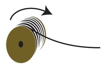
Roll the cable off the spool instead of spinning it off the spool end to prevent putting a twist in the cable for every turn on the spool. When laying cable out for a long pull, use a "figure-8" on the ground to prevent twisting. The figure 8 puts a half twist in on one side of the 8 and takes it out on the other, preventing twists. Installing Swivel Pulling Eyes on Fiber Optic Cable Cable manufacturers install special strength members, usually aramid yarn (Dupont Kevlar), for pulling. Fiber optic cable should only be pulled by these strength members unless the cable design allows pulling by the jacket. Any other method may put stress on the fibers and harm them. Swivel pulling eyes should be used to attach the pulling rope or tape to the cable to prevent cable twisting during the pull. Procedure For Installing Swivel Pulling Eyes: 
Strip the cable jacket and cut back all fibers to the end of the jacket, leaving the aramid strength members only. Separate the aramid yarn into two bundles and loop it through the swivel eve in opposite directions. Tie knots in each bunch at the eye and loop the strength members back to the cable jacket. Tape the strength members along the jacket and up to the pulling eye. How To "Figure 8" Cable for Intermediate Pulls in OSP Installations On very long OSP runs, typically longer than approximately 2.5 miles or 4 kilometers, it may be necessary to use an automated fiber puller at intermediate point(s) for a continuous pull or pull from the middle out to both ends (midspan pull.) When laying loops of fiber on a surface during a pull, use “figure-8” loops to prevent twisting the cable. The figure 8 puts a half twist in on one side of the 8 and takes it out on the other, preventing twists. 
Use this procedure for pulling from one end: Pull the cable out of the conduit or innerduct and lay on the ground in a large "figure 8" pattern. The size of the "8" will be determined by the size and stiffness of the cable, but 6-12 feet (2-4 m) is a common size. The end of the cable will be against the ground - you might want a tarp or plastic sheet to keep the cable clean. Pull slowly and carefully lay the cable in the figure 8 pattern to keep it from becoming kinked. Using several installers, pick up the cable and flip it over so the end to be pulled to the next location is on top. Attach the end to the pull rope with appropriate swivel pulling eyes and continue the pull. For a midspan pull, use these directions: This procedure eliminates having to flip the cable in the Figure 8 on the ground over. Place the cable reel a mid point on the long span (ensuring the maximum pulling length in either direction would not be exceeded). Pull the one end of cable through the conduit to one end of the span. Roll the cable off the reel and Figure 8 the remaining cable on the ground. The end on the cable will be on the top of the figure 8. Pull the second end of the cable through the conduit to the other end of the span. Bend Radius Do not exceed the cable bend radius. Fiber optic cable can be broken when kinked or bent too tightly, especially during pulling. If no specific recommendations are available from the cable manufacturer, the cable should not be pulled over a bend radius smaller than twenty (20) times the cable diameter. After completion of the pull, the cable should not have any bend radius smaller than ten (10) times the cable diameter. Vertical Cable Runs Drop vertical cables down rather than pulling them up whenever possible. Support cables at frequent intervals to prevent excess stress on the jacket. Support can be provided by cable ties (tightened snugly, not tightly enough to deform the cable jacket) or Kellems grips. Use service loops can to assist in gripping the cable for support and provide cable for future repairs or rerouting. Installing Premises Cable in Cable Trays Fiber optic cable is often installed in cable trays in premises applications. Cable trays should not be shared with copper communications cables as their weight may harm the fiber cables. Likewise, large quantities of fiber cables in a tray may put too much pressure on the cables on the bottom. In applications where cable trays are used for copper communications cables, it may be possible to suspend lightweight fiber cables below the cable trays. Use of Innerduct It may be prudent to install critical indoor fiber optic cables inside bright orange “innerduct” to ease cable installation and protect it from future damage. Bright orange innerduct will identify fiber optic cable to any workers at a later date and possible prevent damage. The additional initial cost of the innerduct may be offset by the simplification of the installation saving worker time. Use Of Cable Ties Fiber optic cables, like all communications cables, are sensitive to compressive or crushing loads. Cable ties used with many cables, especially when tightened with an installation tool, are harmful to fiber optic cables, causing attenuation and potential fiber breakage. When used, cable ties should be hand tightened to be snug but loose enough to be moved along the cable by hand. Then the excess length of the tie should be cut off to prevent future tightening. Hook-and-loop fastener ties are preferred for fiber optic cables, as they cannot apply crush loads sufficient to harm the cable. Fire Stopping Indoor cables will have to meet fire codes and pass inspection, so every cable that penetrates a fire-rated wall will have to be firestopped. All telecommunications firestopping must comply with applicable codes and standards. All penetrations must be protected by approved firestops. Fire stopping compounds and devices shall be used whenever a fire separation has been breached by an installation. In most locals the breaching of a fire separation will require physical monitoring until it has been repaired. Check with the “Authority Having Jurisdiction” for specific requirements on the project before commencing work. Grounding and Bonding Conductive cables require proper grounding and bonding for applicable conductors. Although most fiber optic cables are not conductive, any metallic hardware used in fiber optic cabling systems (such as wall-mounted termination boxes, racks, and patch panels) must be grounded. Ground systems shall be designed as specified by the NEC and other applicable codes and standards. Most telecom rooms have a grounding bus bar which has a high quality building ground and connections to devices that require grounding. Splicing and Termination The processes of termination and splicing are covered in detail in Chapter 7. Terminations and splices in the field have no unusual requirements other than a need to find adequate dust-free space with moderate temperatures for working. Splicing Outside plant splicing is usually done in a special splicing trailer or truck. Inside the truck is a climate-controlled splicing lab with adequate bench space for working with the cables and splice closures. Sometimes, it’s necessary to splice in the open, in a small tent or even in an aerial bucket. The installer has to be able to cope with the conditions found in the installation. In extremely cold conditions, a heated facility will probably be necessary as cables become stiff and equipment hard to operate. Hot climates may be easier on the processes but are equally uncomfortable for the installer. Ideally splices should be tested with an OTDR as soon as they are made and before placing it in a splice tray. Fusion splicers give an estimate of splice loss, but it’s just an estimate. The OTDR can confirm the quality of the splice, giving the installer an assurance that the splice is good and the splice closure will not have to be reopened to redo a bad splice. Extreme care should be taken when placing splices in splice trays and arranging buffer tubes or fibers in the closure. One problem that occurs much too often is the fibers are broken as the trays and closure are assembled. Finding breaks in fibers inside the closure is difficult since they are too close to the splice to be resolved by an OTDR. If the splice is near enough to allow tracing with a visual fault locator, it may be found with visual inspection. Cables must be secured to the splice closure and sealed properly. Generally loose tube cables will have the tubes extending from the entrance of the closure to the tray, where they are secured, then approximately 1 meter of bare fibers are organized in the tray after splicing. Care must be taken to properly bond electrical conductors such as the armor on some cables or center metallic strength members to the closure and at each end. All closures must be sealed to prevent moisture entry. Closures must be properly secured, with the location being determined by the installation type, and excess cable properly coiled and stored. This may be in a pedestal or vault, on a pole or tower or buried underground. More on splicing . Termination Termination, at least, is generally done inside a building near the communications equipment, whether terminating outside cable plants or premises cables. The installer may still have problems with finding adequate space, for example in a telecom room with rows of patch panel and equipment racks. Hopefully, the cable installer has provided service loops for each cable to allow the cables to be brought to an open area for termination. Many installers use portable fold-up tables or rolling carts to create a workspace where they can reach the ends of the cables. If the building is still under construction, dust can be a problem. Even in completed buildings, air conditioning systems can blow dust around. Be alert for dust and if working in a dusty environment is necessary, clean all the tools, polishing film and connectors as often as necessary. If terminating singlemode cables by fusion splicing pigtails on each fiber, follow the same cautions on placing splices or fibers in cable trays and closures to prevent damage. For direct termination of 900 micron buffered multimode fibers in a distribution cable, allow adequate length to store excess fiber lengths and take care to avoid tight bends that can cause problems with loss of fiber failure in the future. Splice-on connectors (SOCs) often do not require a separate splice tray or closure but can be terminated and placed in the backside of a patch panel. Like splices, each connector should be checked when the fiber termination is completed. Inspect every polished connector with a microscope to ensure polishing was done properly. If possible, test every prepolished/splice connector with a visual fault locator. After both ends of a fiber are terminated, end to end loss should be tested and documented. High loss connectors must be reterminated and it saves time to do it while the installer is already set up on the site. More on termination . 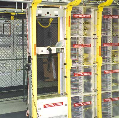
Labeling and Documentation It is usually the installer who terminates the cable that has the job of labeling each termination point. Ideally, the label has been created as part of the design of the cable plant and the installer only has to match the color codes of the fibers to the label, and, if not already placed, stick the label on the patch panel at the appropriate place. This is an important process, as the designation on each fiber will be used to record test data, connection to equipment and be followed during later moves, adds and changes. Doors to patch panels should be marked as to usage and include warnings regarding authorized entry. Cleaning Up The Job Site After terminating or splicing cables, the installer should carefully clean up the job site and leave it at least as clean as they found it, preferably cleaner. All scraps, especially fiber scraps which should be sealed in disposable containers, must be removed from the site. Saving Excess Components Any excess components should be saved for future use, especially restoration. Connectors and cables can be stored along with cable plant documentation so any restoration in the future will have compatible components for use in splicing or terminating cables. During The Installation Inspect all installation workmanship during the installation itself so any problems can be identified and solved before they become major issues. Daily supervisors and installers should review processes, progress on the job and test data. All affected personnel should receive immediate notification of problems and solutions, shortages, etc. Be careful when installating cables to avoid stress, hazards that may snag cables and kink them or installing cables where heavier cables may be placed on top of them. Bundling cables for neatness is fine, but be careful using cable ties. Tightening them can put harmful stress on the fibers (or pairs in UTP copper cables), so hand tighten them and cut off the excess length. Even better, use soft "hook and loop" ties that can be reopened to move cables. Testing the Installed Fiber Optic Cable Plant During the design phase, each cable run should have a loss budget calculated based on the component specifications. After installation, it is necessary to test each fiber in all fiber optic cables for verification of proper installation by comparing measured loss to the calculated loss from the loss budget. Typically, the installer will perform the following tests: Continuity testing to determine that the fiber routing and/or polarization is correct and documentation is proper. End-to-end insertion loss using an OLTS power meter and source. Test multimode cables using TIA/EIA 526-14 Method B, and singlemode cables using TIA/EIA 526-7 unless connector-test equipment compatibility requires another reference method. Total loss should be less than the calculated maximum loss for the cable based on loss budget calculations using appropriate standards or customer specifications. If testing shows variances from expected losses, troubleshoot the problems and correct them. Optional OTDR testing may be used to verify cable installation and splice performance. However, OTDR testing shall not be used to determine cable loss. Use of an OTDR in premises applications may be inappropriate if cables are short. An experienced OTDR technician should determine the appropriateness of the usage. If the design documentation does not include cable plant length, and this is not recorded during installation, read the length from the distance markings on the cable jackets or test the length of the fiber using the length feature available on an OTDR or some OLTSs. Continuity And Polarity Testing Perform continuity testing of optical fibers using a visual fiber tracer, visual fault locator, or OLTS power meter and source. Trace the fiber from end to end through any interconnections to ensure that the path is properly installed, and that polarization and routing are correct and documented. Insertion Loss Insertion loss refers to the optical loss of the installed fibers when measured with a test source and power meter (OLTS). Test multimode cables using TIA/EIA 526-14, preferably Method B (but always document the method used), and singlemode cables using TIA/EIA 526-7 (single mode). Test multimode fiber at 850 and 1300 nm, and singlemode fiber at 1310 and 1550 nm, unless otherwise required by other standards or customer requirements. Test reference test cables before testing to verify quality and clean them often. Cabling intended for use with high speed systems using laser sources may be tested with appropriate laser sources to ensure that tests verify performance with that type of source. OTDR Testing The optical time domain reflectometer (OTDR) uses optical radar-like techniques to create a picture of a fiber in an installed fiber optic cable. The picture, called a signature or trace, contains data on the length of the fiber, loss in fiber segments, connectors, splices and loss caused by stress during installation. OTDRs are used to verify the quality of the installation or for troubleshooting. However, OTDR testing alone shall not be used to determine cable loss. OTDR testing should only performed by trained personnel, using certified equipment designed for the purpose. The technicians performing the tests should be trained not only in operation of the OTDR equipment, but also in the setup of OTDR test parameters and the interpretation of OTDR traces. OTDRs have limited distance resolution and may show confusing artifacts when testing short cables typical of premises applications. If OTDR testing of premises cables is desired, experienced personnel should evaluate the appropriateness of the tests. More on testing . Administration, Management, and Documentation Documentation of the fiber optic cable plant is an integral part of the design, installation and maintenance process for the fiber optic network. Documenting the installation properly will facilitate installation, allow better planning for upgrading, simplify testing and future moves, adds and changes. Unless the user specifies otherwise, documentation of the fiber optic cable plant should follow ANSI/TIA/EIA-606, Administration Standard for the Telecommunications Infrastructure of Commercial Buildings. Fiber optic cables, especially those used for backbone cables, may contain many fibers that connect a number of different links going to several different locations with interconnections at patch panels or splice closures. The fiber optic cable plant should be documented as to the exact path that every fiber in each cable follows, including intermediate connections and every connector type. Documentation should also include insertion loss data and optional OTDR traces. Also see OSP Construction in the FOA Guide Download a free copy of the NECA/FOA-301 Fiber Optic Installation Standard. Read more on installation. |
|
|