
Got
questions? Try the FOA
Guide and use the site search.
If you
don't find it there, email FOA.
Updated 11/21
Topics
(Click on them to jump to that section)
Technology
Manufacturing
Guide?
Q: Is there a guide published by FOA that provides
insight as to the process of fiber optic manufacturing? It's
my understanding that the guide stresses quality and controls
to ensure performance and reduce product loss?
A: We do have a guide
for manufacturers. It is mostly aimed at communications
systems and components manufacture. Here
is a link to download it.
Reflectance
Q: What is the importance of reflectance and all the other numbers in installing and trouble shooting a fiber circuit?
A: Reflectance has always been a secondary issue to connection
loss but has some important issues that need consideration. There are
two basic issues with reflectance, affecting with the output of laser
transmitters and creating background “noise” in a fiber link.
Reflectance can interact with the laser chip itself, causing laser
transmitters nonlinearities or random fluctuations in the output. The
background noise is a secondary issue, but can be seen in ghosts in an
OTDR trace. The light bouncing back and forth in the fiber that causes
ghosts will be added to the signal at the receiver end, adding noise to
the actual signal. Both these effects are more significant on shorter
links, for example FTTH or LANs using PONs (passive optical networks).
We always recommend using APC (angled physical contact) connectors on
short SM links. And most short SM networks do use APC connectors.
FOA tries to stick to the definition that reflectance is the light
reflected from a connection but some others call it “return loss.”
Return loss has been defined generally as the combination of reflectance
and backscatter from the fiber, and that’s how OTDRs measure return
loss. Standards vary in the definition sometimes.
Here is a FOA Guide page on reflectance that gives the basics and
explains how it is tested.
https://foa.org/tech/ref/testing/test/reflectance.html
Electromagnetic Interference
Q: Is there and electromagnetic interference with optic cables?
A: The fiber is glass and the cable is plastic, neither of
which are affected by electromagnetic interference. There is a cable
used in electrical transmission lines called OPGW- optical power ground
wire - that has fiber inside a wire conducting high voltage - doesn’t
bother the fiber at all.
How Light travels In An Optical Fiber
Q: Is there a generalised ratio between
the length of an optic fibre and the length of the path actually taken
by a light pulse inside that fibre? If yes, do OTDRs factor in such
differences in any way? or they such sown the length of the actual path
of the light pulses?
A: Each optical fiber has an effective
independent of refraction. The index of refraction is the ratio of the
speed of light to the speed of light in the material: n=c/v where
n=index of refraction, c=speed of light in a vacuum and v=speed of light
in the fiber.
For an optical fiber, the manufacturer measures the index of refraction
which is usually in the range of 1.47. Corning SMF-28 singlemdoe fiber
for example is specified at 1.4670 @ 1310 nm and 1.4677 @ 1550 nm.
So if you use the equation above, the speed of light in SMF-28 fiber for
a 1310nm pulse is c/n or 300,000 km/s divided by 1.4670 = 204,500 km/s.
When an OTDR measures length, it actually measures the time its test
pulse takes to go to the end of the fiber and return, so the distance is
2X the actual fiber length. The distance is speed x time.
If a fiber is 1 km long and the speed is 204,500 km/s, the time
forlight to travel the 1km is 1/204500 = 0.00000489 seconds or about 5
milliseconds.
OTDR will measure that fiber as 10 ms becasue its pulse has to go both
ways, and it would calculate the length as i km, using that effective
index of refraction of 1.4670.
Back to your original question, the index of refraction is the generalized number based on how light travels in the fiber.
Applications
Managing And Maintaining a Fiber Optic Cable Plant During Its Lifetime.
Q: Are there guides / recommendations for optic fibre cable
life cycle management? (outside plant) including rehabilitation /
replacement timelines together with factors that may alter those
timelines ( such as seismic activity, extreme weather, human
activity-induced fibre cuts etc) also including typical performance
deterioration over the life cycle, and the performance levels at which
replacement / rehabilitation happens. Or does it happen (and is it
normally expected) that operators replace entire sections of fibre (say
400 km) as part of routine maintenance?
A: There is a saying here in the US that in fiber optics “the most common cause of failure is “backhoe fade” in underground cables
and “target practice” for aerial cables.” In other words, damage
caused by humans. We know of many fiber optic cable plants that have
survived natural disasters like earthquakes - in fact there is a lot of
work today using regular cables used in communications to monitor for
seismic activity. Fire can be a problem in remote areas, but often it’s
because the poles are burned causing the cables to fall.
Over the years we have questioned cable manufacturers about the lifetime
of fiber optic cable. They don’t like to make definitive statements but
we have been told that based on the cables installed in the past that
40 years is a probable lifetime for most cables. There are certainly
cables in use today that are over 30 years old already. The glass fiber
is not a problem, it’s the protection from the cables that will
eventually fail. Installation techniques can have an effect on the
longevity. For example splice closures should be sealed properly to
prevent ingress of moisture or dirt. Cables should not be installed with
bends below the rated bend radius or with excess tension.
FOA has always told users that fiber optic cables do not need maintenance (https://foa.org/tech/ref/user/maintain.html),
a response to some people advocating periodic inspection and cleaning
of connections, for example. That’s just more likely to cause damage.
When an accidental break in a cable occurs, we have guidelines for restoration (https://foa.org/tech/ref/restoration/rest.html), and planning for restoration when building the cable plant is very important.
Someday you will certainly want to replace cables, often well before the
lifetime of the cable, but generally because you need more fiber or the
older fiber will not support the network speeds you want for upgrades.
Planning for more fiber by installing more cables can be eased by
installing spare underground ducts when first installing cables - here
in the US, we call this “Dig Once” (https://foa.org/tech/ref/OSP_Construction/Underground_Construction.html). Testing fibers for higher speeds is called "fiber Characterization” (https://foa.org/tech/ref/testing/test/CD_PMD.html) and is routinely done when speeds above 10G or certainly 100G are considered for older fibers.
Knowing that the lifetime of fiber optic cable plants are ~40
years, it makes sense to plan ahead for future applications, installing
lots of fibers, leaving lots of open duct space and choosing network
architectures that will not obstruct upgrades. See the article on
Netly's network above.
Transmitting Multiple Data Types
Q: How do you integrate fiber optic digital communications with other sensing and control systems and platforms?
A: Fiber optic networks generally have lots of bandwidth and
sensors and control systems generally do not require much bandwidth. The
mixing of data streams is generally done by multiplexing the data using
electronics on each end, but one can also do it with wavelength
division multiplexing.
Single Fiber DWDM
Q: Can you do bidirectional links on a single fiber with DWDM? (Dense Wavelength Division Multiplexing)?
A: A company Called Edge Optical Solutions sells
multiplexers for bi-directional DWDM on one fiber by using
adjacent wavelength channels for each direction. It is good to ~400km
with coherent transceivers but cannot use fiber amplifiers for
repeaters.
Identifying Users On A PON Network
Q: How or what testing tool or technique can I
use to verify whether there is a live customer w/ONT
working on any fiber i may select @ a splice
enclosure prior to getting further down the cable
and to the MST service terminal. All our
fibers have light on them leaving the CO so when we
go into a splice enclosure to pick a fiber to
connect a drop to, to service a home, they are
usually all lit up in that enclosure.
A: The simple answer for a tool or technique
that can tell you if a customer is connected on an
output of a PON splitter is “documentation.” If you
know where each fiber is connected going downstream.
Then the IT person who programs users into the
system can tell you if that fiber is connected to a
customer. There is a possibility that there is a
test solution. Have you ever heard of a “fiber
identifier”? It’s a gadget that can tell if there is
signal in a fiber and some can identify the
direction it comes from. What I don’t know if the
unit can somehow indicate bi-directional traffic.
Nobody we contacted seems to know either.
Slow
Internet After Conversion From DSL To FIber
Q: Could
you please help me understand why I am getting a slow connection
(the same as when I was using anADSL box and sometimes even a
bit slower) while having a fiber optic connection to my home
(FTTH then RJ45 between wall & iMac)?
I am using an old iMac from early 2009 but the cable needed is a
regular RJ45, so I do not see why it should not take the high
speed connection...
As a matter of fact, it still takes several seconds (3 to 6 or
even 12) for some pages to load...
A:There
are several possible reasons your Internet is slow loading
pages.
The fiber optic link to your residence may have little or
nothing to do with the speed you see. If you use a speed test to
check the speed of the connection, it’s probably going to show
faster speeds, but it generally only tests the connection to
your ISP - Internet Service Provider - not to the Internet or a
remote data center. The actual connection to the data
center sending you the pages you request may be hundreds or
thousands of km long and through many switches, so that could
affect the speeds.
The major problem we see is the speed of the connection of your
ISP to the Internet. If they have many subscribers, the “traffic
jam” is at their connection. This is generally easy to see over
the time of day. In the evening when many people are streaming
TV or movies, it sends to get much slower, just like automobile
traffic during rush hour. At times when fewer people are online,
speeds will be faster.
We have exactly the same problem here in Santa Monica. Our
Internet over a cable modem tests at 100-200 Mb/s but pages are
slow loading because so many people are on the network at once.
However, I also suspect your 12 year old iMac. The typical web
page is more complex than a decade ago and may contain hundreds
of files including graphics that have to be downloaded and
assembled for you to see the page.Newer computers are much
faster and software is more efficient at handling large pages.
Campus Network Expansion
Q: Any advice for expanding a campus fiber optic network?
A: Here are some thoughts:
- Building
to building can more easily be done with indoor/outdoor
cable to get past the 50’ code limit for OSP cable.
- Many
campuses have ducts but they are often crowded. Microducts
or fabric ducts are often the solution even if you have to
pull out an older cable to pull in new microducts into one
old duct.
- Microducts
and blowing microcables are gaining lots of traction for
their practicality.
- Microducts
and microtrenching can be what we call “construction without
disruption.”
- We
are seeing more and more directional boring - works fine as
long as you know where other buried utilities are! Many
contractors need to learn more about underground location.
- People
are finally getting the idea about singlemode fiber - now
it’s probably cheaper than multimode.
- Passive
optical LANs can save money. Biggest advantage is the
upgrade from GPON to 10GPON is seamless - you can even run
both simultaneously, e.g. for a student system and a
faculty/research system.
- High
fiber count cables are tempting, but require special
handling and lots of manhole/handhole space.
- We’re
working with a Corning “Pioneer” (retired engineer) on
trying to educate installers about bend radius violations,
esp when pulling large fiber count cables.
- Most
installations shortchange manhole/handhole space.
- Aerial
is sometimes used. Lashing to a messenger is probably best.
We worked with a school in Canada last year trying to use
short lengths of ADSS and it was not cost effective nor was
their much applications support for short ADSS links.
- Line
of sight wireless (RF or optical) works across highways and
may be cheaper than construction for fiber.
Minimum
Link Length
Q: I have a question regarding minimum fiber optic
distances for horizontal runs. Is there a minimum distance for
a horizontal fiber optic run? Any information regarding this
would be greatly appreciated. Thank you for you help!
A: The answer to your question is for the most part no,
there is no minimum distance for a fiber optic link. For
example, fiber is used in offices, data centers, etc.
sometimes connecting equipment on a single rack. And there are
many fiber optic links used on platforms - aircraft,
helicopters, ships, etc. - and in command posts.
Most of the Ethernet standards are based on a 2m minimum, but
also most are defined by a maximum length. For multimode
systems, the max length is mainly a bandwidth issue, so
shorter links are no problem.
For singlemode links, the bandwidth is not an issue, it’s the
power budget, limited by the transmitter power and receiver
sensitivity, translated into the loss of the cable plant. But
for receivers, often they have not only a minimum input power
limited by their baseline noise but also a maximum power they
can have before saturating and causing high bit error rates.
See “Power
Budget” on this page in the FOA Guide. So if a
singlemode link is short, the receiver can be overloaded so an
attenuator is used at the receiver.
There is a secondary problem with singlemode systems,
reflectance. Reflections from connections can cause problems
with both transmitters and receivers, a topic covered in the
link given above. The reflectance problem can be solved with
APC connectors.
The FOA
Guide has many pages on links, networks, reflectance,
testing, etc. that you may find helpful.
What
Is A Ring Network?
Q: If according to the TIA or ISO structured cabling
standards the fiber optic campus backbone must be
star-hierarchical type, how should a fiber optic "ring" be
built? to always ensure connectivity on a LAN?
A: A “ring” network consists of a series of links
connecting equipment (nodes) in series until the last one
connects back to the first. Since the links are communicate in
both directions, the network can still operate if any one
cabling link or equipment fails. Today, survivability is
usually ensured by using a “mesh” network; the architecture of
data centers, the Internet or phones. In addition to having a
series connection of nodes, there are other interconnections
that provide for multiple alternative paths. See Networks
in the FOA Guide.
Crossed
Connections
Q: If a FO connector is crossed connected i.e Rx
connected Rx and Tx to Tx at both end, will it works?
I know in theory it will not due to light circuits
arrangement, but is there SFP in the market can tolerate
that?
A: We do not know how a SFP could sense and change
polarity unless it had an optical switch inside the module. A
transmitter is a laser or LED and a receiver has a
photodetector. Unless one could have the devices change
function, changing polarity would be impossible.
FTTH
GPON
Q: Can you guide me some websites or pages where I can learn more about GPON Technology please?
A: FOA Guide has a big section on FTTH and OLANs using GPON technology. Follow those links, Also FOA has a new book, The FOA FTTH Handbook you can order from Amazon.
Cheating
On Link Length
Q: I have a fiber run for a camera starts at location A
to location B it is 467 feet. Location B jumpers through
to location C which is 2060 ft at location C. Transceivers
areSFPs ONLY GOOD UP TO 1800 ft, but this company only has a
multimode system. Is there something i can do to make this
work?
A: It might work as is, since electronics are usually
quoted with conservative specs and will work farther than
specified most of the time. If you have several SFPs, test the
output power to see if it exceeds specs and choose the 2 ones
with highest power. If that still doesn’t work, contact SFP
manufacturers for higher power units.
Errors
In A Data Link
Q: What is the significance of bit error, and what is
the acceptable rate for communications and submersible
vehicles?
A: On any data link, there is an acceptable amount of
error that can be tolerated. If it’s a digital voice link, a
BER 10E-6 (1 error in 1million bits) is acceptable without
affecting voice quality. If it’s a link to your bank, the
typical standard is a million times higher (10E-12). Link
protocols usually have ways to determine BER, like attaching a
checksum to the end of a data packet and having it checked at
the receiving end. If a error is suspected, the packet will be
discarded and retransmitted. Here is a tutorial
on BER and an explanation
of errors in a a fiber optic link.
GPON
Q What is normal Range for good power in an FTTH fiber?
A: The GPON specification for downstream power from the
OLT is OLT transmitter power should be 0 to +6dBm and link
attenuation in the range of 13 to 28dB, which says receiver
power the ONT must be a maximum of 13 dB less than +6dBm or
-7dBm and a minimum of 28 dB less than 0dBm or -28dBm, so -7
to -28dBm at the receiver.
Upstream, the similar calculation is ONT transmitter -4 to
+2dBm and the receive power at theOLT is -11 to
-32dBm.
See http://thefoa.org/tech/ref/appln/FTTH-PON.html for the
full specifications for GPON.
Reflective
Events Causing Transmission Problems
Q: I have a technical question about reflective events.
I recently assisted to troubleshoot an intermittent SM fiber
link for a customer. The cable was dug up a few years ago and
a fiber contractor has (fusion spiced) a different chunk of
cable into the link to repair it. When troubleshooting the
link, I checked the cable with the otdr. I found that each of
the 12 fibers had a reflective event at the fusion splice.
This was only at the splice tube closest to me. The other
fusion splices in the other tube were virtually invisible (as
they should be). I'm a little puzzled as to why there are
reflections at the fusion splices. I did a little research,
but couldn't come up with a good answer as to what is a
possible cause of the reflections. (The OTDR also showed a lot
of ghosting on every fiber tested) (in some cases it recorded
over 40 ghost events) Although I haven't been able to confirm
that there is high Bit error rate due to the transceiver not
providing these statistics, (except for 3 out of 10 pings
fail) I am suspecting that High reflectance is possibly the
cause of their unreliable fiber link.
A: Reflectance is a big problem in SM links,
especially short links. If you are seeing lots of ghosts, I
suspect the link is very short. Fusion splices can have
reflectance if the splicer is improperly set and the fusion is
incomplete or has bubbles. Those splices should have not only
have reflectance but higher loss. The solution is to open up
the closure, use a VFL to find the reflective events and redo
the splices.
POTS
over Fiber
Q: I would like to know if there is information on your
website that explains "POTS OVER FIBER"?
A: POTS - the acronym for “plain old telephone service”
- is digitized to transmit over fiber. In the early days (late
70s and 80s) it was simply T-carrier with a fiber converter.
By the end of hte 80s it was ATM and SONET. More recently,
it’s all going to carrier Ethernet since 99%+ of the traffic
is data not voice or PONs (passive optical networks) for fiber
to the home.
Can I Build A GPON Network
With "Taps"?
Q: Can I build a GPON network where I do a drop to one
subscriber then continue to the next subscriber for another
drop and so on?
A: There have been examples of this type of “tap” drop
proposed, for example in rural areas for drops to
widespread subscribers on a longer network than is typical for
FTTH. It’s just a version of a cascaded splitter network. with
taps that just do a 2 way split. The taps used are typically
90/10 taps, where 10% of the power is tapped off for the drop.
There are some important issues to consider - Since you are
dropping 10% of the power at each tap, you are limited by how
many drops you can have. If you calculate the loss
budget - after the first tap, you have 90% power left less the
excess loss of the splitter (~0.3-0.5dB). The tap power is
down ~10.3 dB and the through power is down ~0.6 dB. At the
next tap, you use the same formula plus you add the loss
of the fiber to that tap and so on until you reach the GPON
limit. It’s a pretty complicated process to design, but
you can see that with these power losses you will not get a
large number of drops in a GPON network with 28dB max power
budget. We did a rough calculation and 20-24 drops may be
possible depending on the fiber lengths.
This network will probably be much more expensive and more
distance limited than simply running a cable with many fibers
and dropping fibers from that cable with midspan entry.
Couplers are expensive, fiber is cheap. We also do not know
the issues with the large differences in transmission times
between the first connections and the last ones, which depends
on the length of fiber in the systems. That may require some
programming at the OLT.
Do
We Need Repeaters For 30 Mile Link?
Q: I need to design a 30 mile (~50km) link. Will regeneration
like a fiber amplifier be necessary?
A: It depends on the comms equipment but I doubt you need
regeneration. 30 miles is 50km, only 10dB of loss for the
fiber at 1550nm, maybe 10 splices at <0.1dB adds only 1dB
loss and another dB for connectors on each end. I think you
probably can find equipment that runs on 12dB loss budget.
That said, most new high speed systems (>10G) have 20km
versions then go to expensive long haul coherent systems. So
talk to the communications equipment manufacturers and see
what they say. If you do need a EDFA, they are not that
expensive but the site is expensive and requires power (+
backup). See if it’s possible to put the EDFA in the end
facilities to get enough power for the whole run.
Connecting
WiFi Access Points In a Passive Optical LAN
Q:
If we install GPON passive fiber optical LAN in a new hotel,
would one need to run fiber to every AP? Since every hotel room
needs an AP this gets expensive. Any suggestion on the simplest
and less expensive way of connecting Fiber Cable to an AP
in the hotel room?
A: You do
not need a fiber to every wireless AP in a GPON passive optical
LAN (POL). The AP needs a UTP (Cat 5e/6) cable with Gigabit
Ethernet and POE (Power over Ethernet) capability. The POL
fiber should terminate in a multiport switch that has a
fiber input and then 4 or more UTP/POE outputs for the wirelses
APs. That’s the cost saving architecture of a GPON POL. See this
page in the FOA Guide:
http://www.thefoa.org/tech/ref/appln/OLAN-POL.html
You should
also check out the APOLAN website (http://www.apolanglobal.org)
for more information on hospitality applications with POLs.
Wireless
Infrastructure
Q:
I am wondering how the landscape will change as the nation moves
from 4G-LTE to 5G. Will it use the same network as currently, or
will the network need to be updated or replaced? To what extent
will 5G be dependent on wireless vs fibre optic? Will the
infrastructure nationally move more toward an underground wired
one, rather than a Radio Access Network?
A: The
wireless network is totally dependent on fiber optics for it’s
communications backbone. The “wireless” part is the connection
from an antenna to the mobile device. From that point, the
network is cabled, mostly fiber already and soon to be all
fiber.
4G/LTE and
soon 5G in urban areas is moving to “small cells” with about 10X
as many cell sites covering much smaller areas. Every small cell
site needs a couple of fibers. Metro backbones will require very
much larger fiber counts, especially with C-RAN (centralized
radio access network) architectures now being implemented.
An example
is Santa Monic, CA where we live. It has about 200K citizens,
8.9 square miles(about 23 sq km), but has planned for 600 small
cell sites, spread over multiple service providers.
At FOA we
see wireless as one of the most active areas for fiber, along
with data centers.See http://www.thefoa.org/tech/ref/appln/wireless.html
Fiber
Ports Or Media Converters?
Q: Should I Buy A Switch With Fiber Ports Or Use
Media Converters?
A: I’m assuming you
are thinking of using a switch with copper Ethernet ports and
a media converter instead of a switch with fiber ports. The
downside is that it adds complexity and increases the chance
of failure. My analogy is something my primary flight
instructor told me many years ago - multiengine planes are not
safer because having two engines doubles your chance of having
an engine failure. IBM still says that most network problems
are cabling problems. Using media converters adds more
electronics, more power supples and more cabling connections.
Passive
OLANs in Hotels And Resorts
Q: Are passive OLANs a good choice for hotels or
resorts?
A: Passive Optical
LANs are enterprise networks based on fiber to the home (FTTH)
technology not Ethernet over structured cabling. The FTTH
network is usually using GPON standard equipment over one
singlemode fiber with passive optical splitters that provides
basic Level 1 and 2 network functionality. This is not
Ethernet but carries Ethernet over the GPON protocols at 2.5G
downstream and 1.25G upstream.
Passive OLANs offer several advantages over conventional
Ethernet switches and structured cabling, including much less
cost (~50% capital expense and ~20% operating expense),
much lower space requirements (see the link to the library
photos below and note the two racks of equipment that support
4000 drops), longer distance requirements (to 20km), easy
expansion (these are systems designed for hundreds of
thousands of users) and easy management (when you have
hundreds of thousands of users, that’s important.)
For hotels, convention centers and similar facilities, the
ease of upgrading to a passive OLAN is a big advantage - one
fiber goes from the computer room to a splitter where it can
serve 32 switches of 4 ports each. That’s right, one fiber can
support 128 users! It can support anything that a network can
- wireless access points, security cameras, secure entry
systems, VoIP phones or POTS phones - anything that will run
over a conventional network.
Duplex
Communications Over One Fiber
Q: Is true duplex over a single fiber possible, or is
more like a shared time-domain technique in a quasi-duplex
mode? I would guess that true duplex would lead to
interference problems.
A. Bidirectional links
are widely used - that’s how FTTH PONs work. They use
splitters to combine/split the signals and one wavelength
downstream and another upstream. See Fiber
Optic Datalinks and for FTTH FTTH
Architectures.
Installation
Fiber Optic Color Codes Reference Chart
Q: Has anyone made a fiber optic pocket reference chart that has cable
color orders, frequencies, or other commonly used info on it?
A: The FOA has a page on its Online Guide that covers color codes
(https://foa.org/tech/ColCodes.htm). It is the most popular page in the
FOA Guide! It works great with a smartphone.
Where
In The US Do Contractors Need Licenses For Fiber Optics?
We often
get asked where in the US do contractors doing fiber optic
installations need licenses. We found a good website for that
information, the NECA -NEIS website. You might remember
NECA-EIS, as they are the partner with the FOA in the NECA/FOA
301 Fiber Optic Installation Standard. NECA is the National
Electrical Contractors Association and NEIS stands for National
Electrical Installation Standards. They have a very easy to use
map and table that gives you data on every state in the US, so
mark these pages for future reference.
NECA/NEIS
http://www.neca-neis.org
(See “State Regulations”)
http://www.neca-neis.org/state/index.cfm?fa=state_regs
(all electrical licensing)
Low Voltage: http://www.neca-neis.org/state/index.cfm?fa=specialty_licensing
Good
Technical Website For Installers
American
Polywater (http://www.polywater.com/)
has one of the best technical website for cable installers. Check
out their website, especially “Videos,” “Engineer’s Corner”
and “Calculators.” http://www.polywater.com/NNNBSL.pdf
Underground Utilities Location
Q: From an OSP engineer: Is there a resource for
underground utilities that we could use on our engineering designs? I
know some counties offer this info but is there a single resource for
all?
A: If you are in the US, the Common Ground Alliance (https://commongroundalliance.com , https://commongroundalliance.com/Tools-Resources/Resources-Library/Toolkits)
is a resource for designers and contractors looking for information on
underground utilities. Their “CGA Best Practices”
(https://bestpractices.commongroundalliance.com) is the best reference
for damage prevention.
Otherwise, the local authorities and utilities are the best source. The
department that issues permits is usually the place to start.
Even with that information, it is recommended that the contractor do
their own search using underground locating equipment before digging.
You may find this page in the FOA Guide on underground cable construction useful. ( https://www.foa.org/tech/ref/OSP_Construction/Underground_Construction.html )
Fiber
Optic Safety Poster
We've had numerous requests to reprint our guidelines
on safety when working with fiber optics, so we have
created a "Safety Poster" for you to print and post in your
classroom, worksite, etc. We suggest giving a copy to every
student and installer.
Splicing Pigtails On A Cable
Q: I seem to be having an issue finding fiber protection sleeves
that can slide over the 3mm patch cable. I bought a sleeve that said it
with made for “single fiber fusion” but the thru hole which I would
side the cable thru prior to fusion is too small for the patch cable.
When I try and look on-line for specifications for the thru-hole size,
prior to fusion final melting of the glue in the sleeve, all I find are
post-melting diameters, none which are even close to being able to
handle the 3mm patch cable.
A: Splicing pigtails involves splicing the fibers only and the
cables are secured separately. The usual method of splicing on pigtails
is to splice the fibers and use the heat shrink tube to seal the splice
and the fibers from the outside air and protect it from stress. The
splice is placed in a splice tray. On either side, there is 2-3 feet of
fiber exposed from the cables being spliced. The splice tray has clamps
for all of the cables being spliced on the edges of the tray and the
fiber to the splice is coiled neatly on the splice tray. The jacket of
the pigtail is clamped at the edge of the splice tray but ends there,
so only fiber is coiled in the tray. If you try to coil fiber, the bulk
of the cable can get to be a problem where it’s coiled with the bare
fiber. You can get heat shrink protectors for fibers of 250 to 900 micron diameter buffers, but not for jacketed cables.
Gel Leaking From cables
Q: We have several instances where gel from inside
the fiber optic cable has leaked into the splice closure. I have seen
some information about sealing the ends of cables so that this doesn’t
happen but cannot find a specific method or procedure for this or what
to use for a sealant. Is this something that is common practice for
outside plant cables? The gel creates a mess and definitely makes
reentry for additional splicing more difficult. If there is a way to
prevent or minimize this I would like our technicians to start
implementing it.
A: When you install the cable, after inserting the cable
in the splice closure and/or the budder tubes in the splice trays, seal
the end with silicone RTV adhesive. It needs some time to cure but that
should prevent the gel leakage. Or next time, order dry water blocked
cable which will not have this problem.
Interpreting Customer Spec For Cable Plant Loss
Q: I am currently being challenged by my
customer on some testing parameters and was wondering if I can
receive your input regarding the EIA/TIA-598B standard.
A: The customer spec: l. Rated attenuation: 0.35dB/km and 0.25dB/km at 1310nm and 1550nm, respectively
As we read the customer spec, this section “L” below refers to the
cabled fiber attenuation coefficient of the cable as supplied to the
contractor, not the installed fiber after splicing and termination.
Thses are typical specifications for today’s high quality fiber. It is
also slightly lower than specifications noted in most standards today,
e.g. 0.4 dB/km at 1310 nm is more common. See https://foa.org/tech/ref/basic/fiber.html in the table at the bottom of the page, noting OS!/G.652 fiber specs.
After installation, splicing and termination, the total loss of a fiber
link includes the losses from splicing and termination, plus any passive
devices like PON splitters that may be installed in the link. When
calculating the loss budget (https://foa.org/tech/lossbudg.htm) to
compare to actual test test results, splices may be calculated at
0.15-0.3 dB each and connectors at 0.3-0.75 dB each, adding to the end
to end loss and affecting the calculation of dB/km.
For example, 10km fiber with 4 splices and two connections (the ends) would have a total loss of:
Fiber: 10 km @ 0.35 dB/km = 3.5 dB
Splices: 4 @ 0.15 dB each = 0.6 dB
Connections: 2 @ 0.3 dB each = 0.6 dB
Total link loss = 4.7 dB
If you calculate dB/km for the installed link, it becomes 0.47 dB/km,
even though we used the lowest loss specs for splices and connections.
As stated above, the spec you called out refers to the cabled fiber only
and should be verified by the test documentation supplied by the
manufacturer on the reel.
The loss of the installed link should be calculated in the loss budget
for the link as designed using the given fiber spec plus reasonable
specs for splice and connection loss.
Testing should be done with a light source and power meter (OLTS) and a second test with an OTDR per OFSPT-7 or FOA Standard FOA-1 (OLTS) and FOA Standard FOA-4 (OTDR).
Underground Utilities Location
Q: From an OSP engineer: Is there a resource for
underground utilities that we could use on our engineering designs? I
know some counties offer this info but is there a single resource for
all?
A: If you are in the US, the Common Ground Alliance (https://commongroundalliance.com , https://commongroundalliance.com/Tools-Resources/Resources-Library/Toolkits)
is a resource for designers and contractors looking for information on
underground utilities. Their “CGA Best Practices”
(https://bestpractices.commongroundalliance.com) is the best reference
for damage prevention.
Otherwise, the local authorities and utilities are the best source. The
department that issues permits is usually the place to start.
Even with that information, it is recommended that the contractor do
their own search using underground locating equipment before digging.
You may find this page in the FOA Guide on underground cable construction useful. ( https://www.foa.org/tech/ref/OSP_Construction/Underground_Construction.html )
Markers Required For Underground Fiber Optic Cables?
Q: Are signs required for underground cables like fiber
optic cables? Are they required to have signage so people don’t dig them
up or damage them?
A: In the US the answer is NO. There is no Federal or State law
which requires marking anything other than hazardous liquids and gases.
It is purely a business decision or a moral decision to invest in
signs/markers to protect buried fiber. If a fiber gets cut it can
disrupt 911 service and all kinds of vital communication related to
hospitals, air traffic control, etc.
Distances Between Manholes
Q: What is the standard or max distance between manholes and handholes for fiber optic cable?
A: There are no hard rules, but the distances are determined by a
number of factors. In populated areas, the manholes or handholes would
be situated where you need drops line in front of a building or a
splitter pint for FTTH or conversion from underground to aerial or
underwater cables. From a viewpoint of how far you can go, it’s
determined by: 1. The length of cable on the reel (typically ~5km max,
maybe further for smaller cables, shorter for higher fiber count
cables. 2. The type of the duct, cable and method of installation
for underground. That includes the type of duct, lubricant used, the
number of corners passed, pulling equipment (pulled or blown) and
the tupe of cable - most limited to 600 pound tension. Cable
manufacturers and American Polywater (lubricants) are good sources of
information here. 3. Aerial cable can have quite long spans, esp. using
the moving reel method, which can be limited by the length on the spool.
Gloves
for Fiber Techs
Q:
I was wondering if as part of the safety rules, in addition to
glasses, if it is recommended to use gloves.
If that the case, would you recommend a specific type of
gloves.
A: FOA
emphasizes the need for safety glasses because of the problem
with fiber scraps flying around, especially when students in
class are learning to strip fibers. Proper safety glasses have
side shields that provide more protection than regular
eyeglasses. For eyeglass wearers, prescription safety glasses
are available at very reasonable costs that are much more
comfortable to wear than wearing safety glasses over the
user’s prescription eyeglasses.
We only recommend gloves when working with cables that have
sharp metallic armor in them or some heavy outside plant
cable. The metallic armor can cause serious cuts if one slips
when splitting or removing it. The gloves to use are the
kevlar gloves used to prevent cuts (they are also used for
chefs working with sharp knives.)
Once the cable is opened and you are dealing with buffer tubes
or bare fibers, gloves like the ones used for cables can make
the work difficult because gloved hands are clumsy. Tight
surgical rubber gloves might work for some, but still make
working with bare fiber difficult and provide limited
protection. There we recommend bare hands and being very
cautious.
Height
Of Aerial Fiber Optic Cables
Q:
Is there a code standard for how high from the ground a for a
fiber optic cable running through a residential yard? if yes,
please provide the standard or point me to the standard.
A:
If we go by NEC 2020, the height is 8 feet,above roofs. with
this qualifier. No driveways just over grass. Art
/section 770.44 B. Also 800.44 A 4 states 12 inches between
electric service and Fiber optic cable. But service has to be
12 feet at house so I would say 11 feet above grass. If
driveway is there, Residential 15 feet for service,
electrical, so fiber at 14 feet.
Seal
End Of Cable
Q: For
aerial OSP cable, are there any problems with leaving the end
of the cable open or should it always be put into a closure of
some kind?
A: The
open end of the cable allows moisture to get into the cable
and can be a problem.
I see several scenarios here. If the cable is installed and
waiting for splicing, it could be a matter of time. If the
work is to be done soon - a week or two - leaving it open is
OK, but if the time is longer or you prefer being careful,
just seal the end of the cable by wrapping it with plastic
electrical tape. The end will be opened up for splicing;
about 2m of cable needs to be stripped to splice it, so a few
days exposure is OK, but long term we’d recommend a simple
tape seal, the way manufacturers do when shipping cable on a
reel.
Installing
Cable
Q: Below
are specs for an installation. We’ve never installed a Fiber
Optic run this long. Please see below questions and info.
-Fiber Optic cable to be used is a 24 strand Single Mode
application
-Length of run is 7200 m long
-Appears that all the Fiber is on one reel. However do you
recommend having some junction points on pedestals along the
way for testing-maintenance purposes or just one continuous
run if possible?
A: FOA
has lots of information to help answer your questions:
Re underground installation. See https://foa.org/tech/ref/OSP_Construction/Underground_Construction.html
and https://foa.org/tech/ref/OSP_Construction/Underground_Installation.html
in the FOA Guide.
There are other questions you need to ask:
Are there no intermediate connections or drops required? It’s
just one straight fiber run? You should be able to install it
continuously.
What is the installation type? Pulled in conduit or direct
burial?
If pulled in conduit and you can pull in one try, that’s best.
You should use a pulling capstan to limit tension, attached to
the cable with a breakaway swivel pulling eye and use
lubrication. Use the American Polywater guides (https://www.polywater.com/product/polywater-f-fiber-optic-pulling-lubricant/)
for choosing lubricant and decide if you need an intermediate
pull.
Direct burial is simple for a long run, just ensure you have
the proper equipment.
October
2020's Newsletter article about the installation
of a 6912 fiber cable in small conduit prompted a number
of this month's questions on social media. And there were more
too.
Re: Installation
of a 6912 fiber cable
Q: For
this post, "Tight Fit: 6912 Fiber Cable Pulled in 1.25 inch
Conduit”, he asks if they can see one end completely terminated?
A: It takes about 2 full racks of patch panels or one
rack of splice trays. Sumitomo shows the splicing rack here
https://global-sei.com/data-center-solutions/splicing-rack.html.
Most systems using these cables will buy fully populated patch
panel racks with a splice rack for the cable to splice to 6912
fibers terminated in the rack.
Q: And a second question:: How long does it take to
terminate? And over how many panels?
A: A very experienced tech can splice one of these
cables in ~75-100 hours using ribbon splicing.
Q: I assume that's smaller fiber like 80 micron cladding
A: All the fibers in the high fiber count cables are made
with regular singlemode fiber - 9/125micron. TO make the cables
smaller, the buffer coating diameter is reduced to ~200microns
to make the fibers smaller.
Q: How was it prepared with the splice tray and ODF? It
might require a dedicated panel and splice tray.
A: It takes about 2 full racks of patch panels or one
rack of splice trays. Most systems using these cables will buy
fully populated patch panel racks with a splice rack for the
cable to splice to 6912 fibers terminated in the rack.
Q: Is this an actual photo or was the cable installed in
a different type conduit.
A: We were told that is the actual size of the cable and
conduit although not of the actual installation discussed.
Q: What is the minimum bend radius of that cable? What
procedures did they use to maintain that bend radius through
those 90 degree curves?
A: The minimum bend radius is 15X the cable diameter for
that cable (diameter 1.14” or 29mm), about 17” or 435mm.
The conduit bends had to be controlled to be larger than that
radius. See the Fiber U MiniCourse Fiber
Optic Cable Bend Radius
Preparing
Cable For Splicing
Q: Is
there any standard on the preparation length of strip jacket
upto the splice tray. Ideally its better to have a loop of
buffer before getting into the tray if ever the closure has
enough space for slack.. its also nice to put some hose to the
buffer to add on protection. So far, i don't see any standard
and can't support the remarks on what to follow. The practice
was to take note on macrobend and have enough length of fiber
to reach the machine.
A: There
is a lot of variation in the size, shape and design of splice
closures, so the length varies according to the closure and
trays. For loose tube cable, the length of buffer tube from
the entrance to the splice tray and the length of fiber needed
in the tray are given in the directions for that splice tray.
Similarly for ribbon cable, but the variations in ribbon cable
designs often requires special handling and sleeving for the
ribbons. Most manufacturers have specs available online.
Fiber Splicing Cost
Q: What is the standard of costing for fiber splicing and
terminations? Is it per core / per splice or per each cable end
irrespective of the number of cores?
A: That is a very hard question to answer, other than to say ”it
depends. ” The number of fibers is definitely a factor because each
fiber must be stripped, cleaned, cleaved and spliced then placed in the
splice tray.
It also depends on:
- Single fiber or ribbon splicing?
- Type of splice closure
- Type of cable (loose tube, ribbon, flexible ribbon, high density, armored, ADSS, etc.)
- Installation: aerial or underground
- Location: urban or rural
- Set up time (same for low fiber count cable as high fiber count cable)
Most contracts will be considering the number of
fibers but also these factors, and probably they want to price by the
number of fibers, but the price per splice will vary accordingly. We've
seen quotes in the US for prices varying over a 10X range.
Lashing
Aerial Cable With Cable Ties?
Q: I am considering an electrical job installing fiber
optic aerially on a messenger cable.
I have seen the cable tie method of lashing the fiber to the
messenger. Would you recommend this method considering the
cost of a lashing machine for a single project and if so what
would be a good distance between ties for the proper support
of the fiber to the cable.
A: The normal way to attach an aerial cable to a
messenger is lashing the cable with stainless steel wire. If
you use cable ties, you would need ensure the cable doesn’t
droop and the cable ties are designed for outdoor use in the
sun over a long time (stainless steel ones are available). How
long is the span? If it’s more than 100 feet, I think I would
go with lashing. If you don’t have a lasher, you can rent one.
You will need a bucket truck anyway.
Restoration
Time
Q:
Do you have any statistical data on how long (on average) it
takes for a utility network operator to detect and pinpoint the
exact location of a fiber cut?
A:
We don’t have any information on the average time it would take
to find a fiber fault and like all averages, it might not have a
lot of meaning.
Many
fiber optic links today have alarms that indicate loss of
transmission so they tell you immediately when the link goes
down. Identify the link and the fiber connection. Then it
becomes a matter of troubleshooting and eliminating causes.
Sometimes even when reconnected the equipment requires a system
reset to get started.
First
- check the power on the equipment
Secondly:
determine if someone was doing something in the equipment area
that might have caused a problem. We do know of a link that was
brought down because an executive giving a tour disconnected a
live link to show someone a fiber connector! If someone was
working nearby, check that area first - patchcords, cables, etc.
Don’t forget to check work records to see if a crew is working
around the cable plant at that time. It’s possible a crew
installing new cables damaged old ones. See the FOA newsletter
for this month for what installers do on aerial cable plant
https://www.foa.org/foanl-3-20.html or last month for
underground https://www.foa.org/foanl-2-20.html.
If
it appears to be in the cable plant and nobody is working near
it, OTDRs are generally used for troubleshooting. They get you
into the area where the problem is and them it’s finding it
manually. Underground it’s often contractors digging or boring,
overhead it’s just poor workmanship - or as a guy from
Bonneville Power put it, it may be “target practice” although
animals damage aerial cables too.
FOA
has a page on restoration
https://foa.org/tech/ref/restoration/rest.html and some of our
instructors do seminars on it.
Time?
If there are trained techs available, finding the problem can
take less than an hour. If not, it can take a lot longer. Repair
can be hours or days if the proper techs and equipment are not
available.
If
nonstop service is required, alternative fiber routing is the
solution - build a mesh network.
Under
any circumstances, having a restoration plan and repair
materials should be ready. If tech personnel are not available,
a contractor on call is needed.
Cable
Installation Guidelines
Q: I am trying to find information on the
recommendations regarding fiber underground in conduit. I am
looking for industry specific verbiage on the cumulative turn
degrees before you need a handhole or manhole. I believe it is
180 degree cumulative but I can’t find it anywhere.
A: We’ve heard the 180 degree limit mentioned on some
conduit but not for fiber optics. For any fiber optic cable
pulling, the relevant issues are pulling tension and bend
radius.
We know of no specific standards or guidelines on conduit
bends for fiber optics. It has many factors, including conduit
size and type - there are many types, length of the pull,
radius of the bends, type of fiber optic cable and lubricants
used, if any. For the cable, there are thousands of fiber
optic cable designs that vary in diameter from ~3mm to ~30mm
depending on the type of cable and number of fibers, the
stiffness of the cable and the location and type of
stiffer/strength members and the method of installation -
pulling or blowing/jetting. And for locations as far North as
you are, temperature can be an issue as cable gets stiffer
when colder!
For any given installation, corners are generally accommodated
by handholes/manholes and pulling done from handhole to
handhole with figure-8ed cable pulling techniques to prevent
cable damage by excessive tension or bending.
FOA has a section of our Guide on OSP construction: Outside
Plant Fiber Optic Cable Plant Construction and in that
is a section on OSP
installation. For specific cables or conduit runs, we’d
suggest talking to the application engineers at cable
manufacturers who can give specific advice.
Construction
Near Underground Fiber
Q: What is the recommended distance for any new building
construction to build near underground fiber duct channel?
A: We do not know of any standards or codes related to
construction near fiber or other underground utilities. Common
sense dictates that one stay far enough away to prevent
accidental damage, so adding 5-6 meters(15-20ft) from the
areas of construction makes sense.
Pulling
Cable
Q: I’m having trouble finding much information on the
matter. What type of swivel should be used to pull fiber and
what would be the correct way to pull armored fiber.
A: Start on the FOA Guide here and go here for
types of swivel pulling eyes. with https://foa.org/tech/ref/OSP_Construction/Underground_Installation.html
and here are sources https://www.comstarsupply.com/cable-pulling/swivels.html
It’s not common to “pull” armored cable since it’s designed
for direct burial, but a kellums
grip on the jacket will generally work.
Communications
Cables on Utiity Poles
Q:
Is there a standard that service providers such as ISP, FTTH
or cable TV should follow when installing their cables on
existing electric poles. For necessary clearances etc. ?
A: The location of comms cables is in the
“Communications Space.” At the top of the pole is the “Supply
Space” for power conductors and between the two is a “Safety
Zone Space.” It is There are guidelines of various types,
mostly referring to NESC Rule 235. One of the best documents
on this is from Nashville
Electrical Service. This presentation
from Finley Engineering offers a good summary.
"Snowshoes" On Aerial Cable
Q: For
overhead installation, can snow shoes, or other service
loop devices, hold two separate cables?
A: Snowshoes are sized for
different cable sizes and types. Some snowshoes are big
enough for several cables, that’s no problems.
Fiber
and Power Sharing Conduit
Q: We are working on a project that has miles
of underground 7 cell innerduct conduit with existing fiber
already running through one of the cells. Is it possible to
run electrical conductors through the 2 of the other cells?
The conductors would be no larger than 1/0 AWG at 480V or
600V. Both the fiber and the electrical are being installed
for the same use.
A:We questioned several people in the electrical side
that also do fiber work. The opinion is that the electrical
may use the other ducts. If the fiber cable has conductive
members, e.g. armor, it must be properly grounded. And any
cables spliced in manholes need separation and marking. The
concern is over what happens with a dig up, but as long as the
electrical is turned off before restoration begins, there
should be no problem.
Fan-Out
Kits Needed?
Q:I’m
working on some MM fiber and am unsure if I need a fan out
kit. Is there a way I can tell if I do?
A:
Is it 250 micron or 900 micron buffer? Splicing or
termination? Loose tube or tight buffer cable? Generally
loose tube cable with 250 micron fiber needs no fan out
kit for splicing - tubes go to splice tray and bare fibers
are protected in the tray - but probably needs it to
terminate if the fibers are exposed, for eample with SOCs
- splice on connectors. Tight buffer - 900 micron fiber -
does not need fan out kits.
Pull ADSS Cable In Ducts Underground?
Q: Our city is installing a 1.5 mile run, mostly
aerial and we want to use ADSS cable. There are two or three
road crossings where we want to go underground in conduit
installed by directional boring. Can the ADSS cable be
dead-ended, brought to the ground, figure-8ed and pulled
through conduit then continue the aerial installation?
A: The answer is yes this is not an issue and is done
all the time. It is standard procedure. (Thanks to Pat
Dobbins, FOA, the expert on ADSS cables.)
Microtrenching
Q: I recently read an article you wrote in April of
last year about micro trenching..Currently, I am employed
with an underground construction company. Something we have
never been involved with is micro trenching and would like
to possibly get some equipment and training scheduled in the
near future. In saying that, it has seemed to be almost
impossible to find numbers on the price per foot.
Essentially, I am asking if you have any resources to some
up with those numbers or models to maybe use for pricing
purposes.
A: Microtrenching is becoming another tool that
contractors are adopting because like directional boring is
is less disruptive than regular underground construction.
I’m working with one group that’s using microtrenching in CA
cities, installing microducts and a 288 fiber
about the size of a #2 pencil. Cost is difficult to
generalize other than “more than aerial and less than
trenching.” Cost is very dependent on where you are
working and what the local geography looks like. We know one
contractor who claimed to do 5 miles a day in rural
Washington at costs near that of aerial. It’s especially
good in areas with lots of base stone where trenching or
boring is near impossible or cluttered utilities downtown.
Here are a couple of pages on the FOA website about
microtrenching:
Outside
Plant Fiber Optic Cable Plant Construction
Underground
Cable Construction
Microtrenching
Ditch Witch sells equipment for trenching and trains users.
Condux has the equipment for blown cable and offers training
several times a year.
Blasting
Near Fiber Optic Cables
Q: We
have a project where blasting is planned near fiber optic
cables. We find no standards for this. Is it safe for the fiber
or should we treat it like other utilities like gas and water?
A:
FOA
recommends considering fiber optic cables to be similar to gas
lines when blasting nearby. We know of no standards for this but
there are some descriptions of projects requiring blasting near
fiber optic cable installations. Here is a pipeline
company's guidelines for blasting. The guidelines seems to
focus on staying 5m from the fiber optic cable and using careful
blasting techniques.
Markers
For Underground Fiber Optic Cables
Q: I have a general question about above ground
markers for fiber optic cable in conduit. Is there a
recommended spacing for the markers? Is there a standard
to reference for this?
A: We asked some people who make them and they said the
guideline is “line of sight.” The rules for markers are
mainly what information needs to be on them. Of course we also
recommend adding marker tape about a foot above the conduit. I
was curious if there were any legal issues and I found this
interesting page from Cornell Law School: https://www.law.cornell.edu/cfr/text/49/192.707
So I might add to line of sight any crossings of
roadways, rail ways and some markers for bridge crossings.
We have a new section on the FOA Guide: Outside
Plant Fiber Optic Cable Plant Construction that may be
useful.
Terminate
All Fibers Or Just Some?
Q:We
are currently running fiber which will be 12/24, my question
is do we need to terminate every pair even if we aren't going
to be using them or is there an alternative?
A: No
you do not need to terminate all of them and leaving some bare
fibers is often done when there is no planned use for the
fibers or to save money. However, there are some other issues
to consider. You do need some spare fibers ready to use,
either in case of problems or for upgrades. For small fiber
counts, the cost of terminating them all at once will be
cheaper than having to come back to the site and doing it in
the future. The economics are quite different if you have 144
or more fibers, of course. If you leave bare fibers, be sure
to leave enough length to terminate or splice later - about a
meter for termination and 2m for splicing. And protect them
from damage so they can be used in the future.
Removing
Old Fiber
Q: I have several 1000 feet of old 62.5/125 armored
fiber optic trunks under a raised floor that I am
replacing/upgrading to 50u MM and SM trunks. Is there any
guidance on ‘Best Practices’ to follow when cutting these
trunks into more manageable lengths for removal?
A:
Use a jaws-type cutter to cut the cable into reasonable
lengths and remove it. There should be no danger in cutting
the cable up as long as your workers only cut the right cable.
Raised floors often have large numbers of cables - often
including power cables - so its important to ensure the proper
cables are being cut an removed.
Re-routing
Old Fiber Optic Cables
Q; I have a questions about the re-routing of fiber
optic lines that have been in place for a number of
years. Is it a standard transaction in the fiber optic
business to have to re-route fiber that has been in service
for a long period of time. (e.g. >20 years) If
so, is there a best practice for removal from conduit for
re-rerouting?
A; There is no way we would recommend removing and
reinstalling 20-year old fiber cable. First of all, old cable
may be damaged in removal. Then cable and fiber technology has
improved over the years so you can get much better components
today at greatly lower prices. (One industry analyst I know
likes to say that fiber is cheaper than kite string and
fishing line!) Today’s cable designs allow for much smaller
cables with many more fibers (288 fibers in 9.7mm - just over
3/8”) and new conduit designs allow for more cables in a
conduit (microducts and cloth ducts) and easier installation -
blowing in cables and microtrenching are perfect for metro
areas.
More fibers, especially in a big city, is a must. Smart
cities, small cells, FTTH (fiber to the home), ITS
(intelligent traffic systems), V2X (vehicle to vehicle,
infrastructure, etc.) and many other services need lots of
fibers.
Our recommendation is to pull it out and dump it. Install new
ducts and the fiber you need (x10 maybe?) and have new ducts
for future use. Are you familiar with “Dig Once”?
Why A Figure 8 Cables?
Q: What is the reason for wrapping the cable in a figure
eight?
A: When you need to do an intermediate pull, you have
to pull the fiber and coil it on the ground. A simple coil
will put a twist in the cable. Figure-8 coils put in twists of
opposite directions on each side of the 8 making for no
overall twist in the cable. See How
To "Figure 8" Cable For Intermediate Pulls in the FOA
Online Guide.
Maintenance
of Fiber Networks
Q: Can you guide me how to prepare Optical Fiber
Cable Annual Maintenance Proposal?
A: Basically, the
network needs to be installed properly, fully tested and
everything carefully documented. Then no routine maintenance
is required. Most problems with fiber optic networks occurs
when techs are working with it, e.g. damaging cables or
getting connectors dirty when testing, so leaving it alone
is the best plan.
Electronic transmission equipment can be tested anytime to
ensure proper data transmission, but that does not involve
accessing the fiber.
We have several things which may be of help:
You Tube Video: FOA
Lecture 39 Maintaining Fiber Optic Networks
Web page: Maintenance
Getting
Old Cables Out Of Conduit
Q: How do you get old cables out of a conduit when
they are stuck?
A: Usually we are concerned about reducing friction
when pulling cables through conduit, but sometimes you need to
get them out. Here
is a page from American Polywater the leading lubricant
company with advice on the subject.
Designations For Fibers
Q: I'm currently working on a project involving optical fiber
with VMS signs, CCTV cameras and other ITS equipment. I was wondering if
there is a standard or a good practice which describe the typical
assignation for each optical fiber on a 6 fibers cable for
example? By that, I mean :
- fibers number 1 and 2 : VMS;
- fibers number 3 and 4 : CCTV;
- fibers number 5 and 6 : spares
A: There are several ways people assign polarity on duplex links.
The way you suggest is the most common I believe. Use the odd number
fibers to transmit in one direction, even number fibers to transmit in
the other direction and document the color codes.
"Mining" Cables In Data Centers (Cable Removal)
Q: Is there any documentation out there on best practices for data center cable mining? Any help would be greatly appreciated.
A: This has been a topic in premises cabling since first
proposed by NFPA for the NEC twenty years ago. FOA has gotten this
kind of question before for many different circumstances, but I must
admit that I know of no recommended procedures or standards for the
removal of abandoned cable.
Cable “mining” often refers to the removal of
underfloor cable, may apply to cables in trays and is hard to get
information online - search for “Cable mining” and you get links to
sellers of cables designed to be installed in mines (coal, salt,
minerals, etc.) underground!
The biggest problem with removing unused cables is
identifying the cables to remove. Underlloor cables are particularly
bad, it seems, since you have generations of abandoned cables, often
poorly marked, sometimes mixed with power cables. With metallic cables,
you can sometimes use an ancient telephone tool, a “toner” to trace
cables, With fiber you just have to be careful that you identify the
cable before you cut.
It’s always better to remove small sections, especially if you can tug
on the cable and verify it each time before cutting. We’ve seen photos
of an early data center with cable trays 2 feet deep by 4 feet wide full
of about 4,000 fiber optic cables. After seeing that you understand why
the new high fiber count cables (1728, 34456 and 6912 fibers) are
desirable!
Why
We Warn You To Be Careful About Fiber Shards
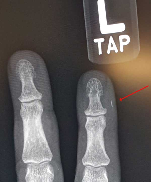
Photo courtesy Brian Brandstetter, Mississauga
Training Consultants
1-844-440-0047
www.fiberoptictraining.com
Fiber/Cable
Fiber Optic Color Codes Reference Chart
Q: Has anyone made a fiber optic pocket reference chart that has cable
color orders, frequencies, or other commonly used info on it?
A: The FOA has a page on its Online Guide that covers color codes
(https://foa.org/tech/ColCodes.htm).
It is the most popular page in the
FOA Guide! It includes a print your own pocket color code chart and one
for your smartphone or tablet - works great with a smartphone.
Multimode
In Premises Cabling
Q:
I wonder when/if single mode fiber will start invading the
enterprise. There's a whole ecosystem, of course, in addition
to physical fiber cabling. Switches, server connections,
protocols, etc. But I'm wondering if you see the industry
moving towards some set of standards using single mode?
A: Today, singlemode transceivers are as cheap as
multimode for 10G and cheaper at higher speeds. Indoor cell
systems (DAS) use singlemode. FTTH PONs (passive optical
networks using singlemode) are being used for LANs because
they are cheaper too. Both technology and costs point to the
advantages of SM. Multimode is the historical design and it's
hard to change. But structured cabling standards (TIA-568, ISO
11801) include singlemode and POLs (passive optical
LANs.)
Storing Fiber Optic Cable On Reels
Q: is there a "standard" for how to store a fiber optic cable reel?
A: This is another detail that has not in my knowledge ever been
included in a standard. However manufacturers usually put a note on the
reel to keep it upright - standing on the edges of the spool sides, not
flat on one side of the spool. If the fiber is to be stored for a
period of time, it should be stored in a cool dry place and the ends
sealed with electrical tape.
(Photo storing cable on reel)
Midspan
Drop Cables
Q: I
am working on a project that has 5 sections, consisting of 5
miles each section, CCTV, detectors, DMS connected by 192
count fiber. We were directed to use the consultants
plans from the first section as a guide for uniformity for the
remaining contracts. The attached fiber detail shows a 4
fiber drop cable going to the ITS device. I was thinking
to take all 12 fibers to the device and back for
redundancy? Also, if we did use the 4 fiber drop cable,
I didn’t understand why they would splice the other 10 thru
cables and instead leave them intact? Is there a preferred
method for a drop cable to a device or just preferences?
A: We are not sure why they do it the way they do.
Perhaps the designer was not familiar with midspan access
which would preclude having to make the other splices. Using a
12 fiber drop cable would be more expensive and perhaps
unnecessary unless the device being connected is in a location
where a small cell site might be located. They may also have
uses for those other fibers that require a connection through
the drop point. We”d suggest to the designer that
midspan access might allow saving the 10 splices at each drop.
Fiber
Flexibility and Longevity
Q:
When I think of glass, I think of a material that is not
very flexible. If you try to bend most glass, it will break.
So it is rather remarkable that you can bend a fiber and
not crack it, even though the strands are quite thin. Perhaps
it's not a good idea to bend fiber too sharply? I was talking
to the people who maintain the fiber network at the university
here. They tell me they have a problem when fiber gets to be
about 15 years old, it will start to become brittle. If you
flex it, it will crack or break. Is this a common problem? How
long can fiber be expected to last before it becomes brittle?
Is fiber that is manufactured more recently have a longer
life-span?
A: Fiber is quite flexible. One demo I did when I taught
classes was to walk up to a large window and push on it,
telling everyone to watch the reflections to see how the glass
flexed. I can flex quite a lot. Like most materials, as it
gets smaller, it can bend more easily because the stress is
less across the cross sectional area. Consider a bar of steel
1” in diameter compared to a piano wire or banjo string. Most
things break because either they are overstressed or there is
some impurity in the material that focuses the stress and the
crack propagates from there. Ever cut glass? You scratch it
and stress it along the scratch line and its maps off - called
cleaving - where the stress concentrates along the induced
fault. Fiber is extremely low in impurities - a matter of how
it’s made from raw materials, not melted sand like most glass
- that’s part of what makes them have such low loss (efficient
transmission) and high strength. A glass fiber is much
stronger than steel of the same size. Corning
explains it here.
The brittleness of older fiber is due to the migration
of moisture up the cable into the glass. The H2O becomes the
OH radical which interacts with the glass to reduce its
strength. Most cable companies say their cable today protects
the fiber well enough that it should last 40 years, but where
fiber is terminated or spliced and exposed to the air, it can
get brittle and be hard to handle in 10 years or more. Older
fiber had shorter lifetimes simply because we learned to make
fiber coatings and cables better at sealing fiber from the
ambient atmosphere.
Fiber
Choice for LANs
Q: Many manufacturers or suppliers worldwide emphasize
the use of OM4 multimode optical fiber for the LAN. Does
single-mode fiber not provide greater bandwidth than
multimode? Do they imply that single mode optical fiber should
only be used for long distance applications and not in LAN
environments?
A: Multimode fiber is acceptable for LANs up to 10
gigabits/second and up to 550 meters depending on the type of
fiber and Ethernet version. See this
page for a complete list of network
specifications.Higher versions of multimode fiber OM2-OM3-OM4
have higher bandwidth capability. OM5 is a version of MO4 that
also supports wavelength division multiplexing with VCSEL
sources in the extended wavelength 850-950nm range. OM1 is a
earlier fiber with a different core size that has not been
designed into new systems for almost 20 years. LANs can use
singlemode fiber for all versions. Singlemode has longer
distance capability (up to 40km) and virtually infinite
bandwidth. See the singlemode specification in the link above.
Singlemode is also used in passive optical LANs that can be
much cheaper to build than conventional networks. See this
page for information on optical LANs (OLANs)
including passive OLANs based on FTTH GPON technology.
Fiber
Lifetime
Q: I am often ask how long the fiber we are deploying
today will last or be useable , I typically say something like
it will last at least 20 years and that no one really knows
how long it can be used. What is the oldest fiber
optic network or longish segment that is still in production
that you know of?
A: Current cables are probably good for 40 years or so.
Today there is some fiber being used by telcos from the late
1980s and lots form the late 1990s and early 2000s. Lots of
OPGW (optical power ground wire) is in use up to 30 years old.
Some of this old fiber is being used at 10Gb//s. But remember
that fiber from 20 or 30 years ago may have limitations on
bandwidth, since both chromatic and polarization mode
dispersion has been reduced in newer fibers for higher speed
networks. And spectral attenuation of older fibers may be
higher and have the water peak at 1383nm that can affect
wavelength-division multiplexing systems. But the weak point
may not be the cable or fiber, but the splice and termination
points where bare fibers may be exposed to the elements. It's
not uncommon to find these fibers have become brittle and are
hard to work with. What we always tell people is if it’s
working, leave it alone. If you want to upgrade to higher bit
rate systems, use fiber characterization to determine if the
fibers are capable of use at higher speeds.
Cable
Bend Radius
Q:
We are working on project where we need to know
difference between short term and long term bend radius for
fiber optic cable?
A: The bend radius for cables is generally specified
under two conditions - under stress, e. g. when being pulled,
it is a radius 20 times the cable diameter. Relaxed, after
installation, it is a radius 10 times the cable diameter. The
relaxed specification, 10X, is considered a long term
specification. Some of the new high fiber count cables have
different specifications, sometimes 15X or 20X under either
condition. Check with the manufacturer for their specific
cable. See this
article on bend radius in the FOA Guide.
Old
Multimode Fiber
Q: We have old multimode fiber and we are still
connecting more equipment to it over greater distances and
need some way to insure the equipment will work.
A: I do not know of any simple formula for figuring
this out. Last time I remember such a formula from around 2000
done for Gigabit Ethernet with VCSELs and the equation
reminded me of the quantum mechanics course I took in physics.
The problem is you have two bandwidth factors, modal
dispersion and chromatic dispersion. Modal dispersion is
highly dependent on mode fill, e.g. the metric “encircled
flux” was developed to define the mode fill of multimode fiber
with VCSEL sources for simulations to estimate bandwidth.
Chromatic dispersion is dependent on the fiber spec and the
spectral width of the source which is better with lasers and
LEDs.
What generally happens is the standards group developing the
network standard, especially IEEE 802.3 for Ethernet, runs the
numbers and specifies a maximum distance for the particular
network and its speed. FOA has a table of these specs here: Specifications
for fiber optic links and systems, including FTTx
105 Micron Fiber?
Q: I have a customer asking about 105um fiber. Does it exist? What is it basically used for? After FOA suggested a clarifying question to the customer: The
fiber is for Power over Fiber(PoF). The construction is 105um fiber
with 125um cladding. The question or assumption would be – The
termination would be the same as 50,62.5 or 8.3um with a 125um cladding?
A: The people who do laser surgery and power over fiber
use special step index fibers and SMA connectors. The power density can
be very high so the heat can build up in the cable. SMA connectors or
the metal ferrule swaged-on connectors are often used for their
all-metal construction with the ability to withstand heat and sometimes
the need to be drilled for special fiber diameters. Because of the high
power, the polish needs to be low reflectance, so we’d recommend using a
wet polish and end with a very fine polishing film - 0.3 microns or so.
Like polishing SM for DWDM.
Cleanliness is very important for these applications. I remember a call
from a doctor doing laser surgery who kept ruining cables because they
were dirty and the high power literally exploded the dirt and pitted the
ends. When that happens, sometimes they can be polished out but often
they are ruined. The same thing happened to the 120 inch telescope at
Lick Observatory when Joe Wampler tried using it to laser range to the
retroreflector Apollo 11 left on the moon. Exploding dust pitted the
aluminization on the mirror.
Replacing
OM1 MM Fiber
Q: We are an automation system integrator in South Africa. We
have a client that has multimode 62.5/125 fibre optic plant
wide. None of the runs between components are longer than 2km.
We intend to upgrade the technology from a proprietary
communication protocol to a standard ethernet protocol at 100
MHZ. The fibre to copper convertors we will be using are using
1300nm light source and have a Fibre Optic Link Budget of
12.8dB for 62.5/125 um and 9.8dB for 50/125 um. The client has
been advised to replace the multimode 62.5/125 with multimode
50/125 cabling and we need to know if this is really a
requirement.
A: Do you know how old the fiber is? It should be what we
called FDDI grade 62.5/125 fiber with a loss of ~1dB/km and a
bandwidth of 500MHz-km at 1300nm. A 2km link should have a
loss of 2dB for the fiber and ~0.5dB/connection - well under
the power budget of the link. 100Mb/s Ethernet variants were
designed for 2km or more on this fiber. There is no reason to
upgrade at this time, 50/125 fiber would not be needed until
Gigabit Ethernet was desired.
Can A
Fiber Optic Cable
Catch "Fire"
Q: While working on a cut-over of a dwdm circuit
something has happened that I am now looking for an
explanation. A transmission fiber emitted "fire" on that same
fiber! We did not see any optical light we saw fire. About 5
cm of fiber burned and remained smoke. What phenomenon
occurred? Are the dwdm amplifiers so powerful enough to
generate fire? Unfortunately I could not get into the station
to take the model of the equipment.
A: We’ve heard of high power WDM systems exploding
dirt of the endface of fiber connectors and damaging them, but
this is a new one. We contacted several technical people in
fiber companies and found that this can happen if there was a
crack in the fiber in the cable near the connector or lots of
reflection perhaps caused by a very dirty connector that
allowed the very high power to heat the cable enough for
combustion. DWDM with many multiplexed signals and a fiber
amplifier creates a lot of power confined to a very small core
of the singlemode fiber. That power can ignite the acrylate
coating on the fiber.
What's
The Lifetime Of Fiber?
Q:
"The utility I work for has some FO cable installed,
some 20 years+ and I am wondering what is industry standard
for the useful life of a cable? This is from an asset
management point of view. I realize that FO cables can and do
last for decades, especially if the work on them is minimized
(ie. splicing for repair or relocation), but what would you
consider a good book value for useful life?"
A: Cable manufacturers have generally made fiber optic
cable for a lifetime of 20+ years and in the last decade or so
we’ve been told that 40 years is reasonable for a cable. But
that means the cable will retain its specifications for that
time frame. Networks, however, do not stand still. In the last
20 years, network speeds have increased by up to 100 times. In
the same time period, the fiber has been engineered to
accommodate longer and faster links. 20+ year old fiber was
installed when speeds were around 1Gb/s, where dispersion was
not an issue, nor was dense wavelength division multiplexing
(DWDM) being widely deployed. So if you are using fiber at
lower speeds, the current cables are probably fine. You might
have trouble splicing older fibers in closures because the
exposed fibers do tend to get brittle.
If you want to upgrade to faster speeds or DWDM, the older
fibers will need testing - we call if fiber characterization -
and here is a page in our FOA
Guide about it: Fiber
Characterization and Testing long haul networks (CD,
PMD, Spectral Attenuation)
Differences
In Fibers
Q: What is the difference between OM3 and OM4 type
fibers and G.654/G.655? They seem to be rated for the
same amount of GBs (10-400) and the only difference
seems to be the multi-mode nature of OM3/4 vs. the single mode
nature of G.654/655. Can they both be used in long haul
communications if laser optimized?
A:
OM3 and OM4 fibers are both 50/125 micron fiber but have
different bandwidth capability. OM3 is rated at 1500MHz-km
while OM4 is rated 3500 MHz-km. OM4 is an evolution of OM3
where design and manufacture allow more bandwidth. More
bandwidth translates into slightly longer link lengths in
faster networks, ~1-10Gb/s. For example, Ethernet at 10Gb/s
will go 300m on OM# and 450m on OM4, which can be important if
it is being chosen for a enterprise network backbone.
The differences in G.654 and G.655 are more complicated. G.654
is singlemode fiber optimized for use at 1550nm for long
distance use. G.655 is “non-zero dispersion shifted” fiber
tweaked for dense wavelength division multiplexing (DWDM) to
prevent secondary problems with high power and closely spaced
wavelengths of DWDM and fiber amplification. It’s the kind of
fiber used in long submarine cables.
Arsenic
Coated Cable?
Q: I was told a contractor installed arsenic
coated fiber optic cable because they didn’t want animals to
chew through it. Is this true?
A: Some cable has
chemicals put in the jacket to make it taste bad to rodents.
We have not found any one who claims to use arsenic, in fact,
we could find no references to what kinds of chemicals are
used.
Why
Do Cables "Go Bad"?
Q: It’s been my observation over ~15 years of
building and managing fiber channel storage area networks that
from time to time cables will fall out of transmission
spec. In terms of communicating with non-storage people,
they in essence, “go bad”. Other than possible damage
due to physical disruption of a cable, or contamination at the
connectors usually caused by a human being
unplugging/replacing, has it been your observation that MM
cables can “go bad”?
A: There are some
possible causes of problems over time. We know of connectors
that fail for several reasons.
- The
biggest cause is with prepolished/splice connectors with
mechanical splices. the assumed problem is the index
matching get goes bad, but that’s highly unlikely. It’s
usually the crimp fails and the fiber pulls out, especially
if it has any stress on the fiber.
- Adhesive
connectors can have a bond between the connector and fiber
fail, more likely on anaerobic connectors.
- Any
stress on the fiber at the connector is bad. Patchcords
should not be left hanging on racks but dressed into
horizontal racks below each patch panel.
- Residual
stress in cables can be a problem - tension or tight bends -
and they may get worse over time.
- Moisture
is always a worry. It takes years to show up, but indoor
cables are not protected from moisture like OSP cables.
- Of
course, transceivers fail too - electronics are generally
very reliable but do deteriorate over time and cause
failures.
We always
say fiber requires no maintenance - set it up right and lock it
up. As you pointed out human intervention is often the issue.
Armored
Indoor Cable?
Q: Can I get an indoor armored 8 core fiber optic
cable?
A: Most cable
manufacturers make indoor armored cable using corrugated wrap
armor to protect cables from crushing loads from other cables
especially in under floor installations.
More
Than “Single” Mode?
Q: We're now using SM fibre so it looks like we
don't need mandrels in the Ref Lead at the Light Source.
The info I have is that we need to make a couple of air coils
35mm to 50mm in diameter. Why?
A: When you launch
from a pigtial laser source through a connector into a
reference cable, you do have several modes being propogated.
It usually takes 100m or so for the second or third order
modes to attenuate. So the coil causes them to be attenuated
by the stress enough to no longer be significant - it’s a mode
filter just like MM. If you do not do this, you will measure
higher loss in the fiber and at connections near the source.
Since most SM has traditionally been long distance, the effect
was small or ignorable, but with short links, it can be
significant.
Followup Q: But how do we explain multiple modes in Single
Mode fibre?
A: When you get the core of the fiber down to ~5-6 times the
wavelength of the light, it no longer acts like geometric
optics (like MM fiber). Some of the light can travel outside
the core (see the note on “waveguide
dispersion”here http://www.thefoa.org/tech/ref/testing/test/CD_PMD.html).
At launch, significant amounts of power are at higher angles
creating short lived modes that are highly attenuated.
Replacing OM1 MM Fiber
Q: We are an automation system integrator in South
Africa. We have a client that has multimode 62.5/125 fibre
optic plant wide. None of the runs between components are
longer than 2km. We intend to upgrade the technology from a
proprietary communication protocol to a standard ethernet
protocol at 100 MHZ. The fibre to copper convertors we will be
using are using 1300nm light source and have a Fibre Optic
Link Budget of 12.8dB for 62.5/125 um and 9.8dB for
50/125 um. The client has been advised to replace the
multimode 62.5/125 with multimode 50/125 cabling and we need
to know if this is really a requirement.
A: Do you know how
old the fiber is? It should be what we called FDDI grade
62.5/125 fiber with a loss of ~1dB/km and a bandwidth of
500MHz-km at 1300nm. A 2km link should have a loss of 2dB for
the fiber and ~0.5dB/connection - well under the power budget
of the link. 100Mb/s Ethernet variants were designed for 2km
or more on this fiber. There is no reason to upgrade at this
time, 50/125 fiber would not be needed until Gigabit Ethernet
was desired.
Old
Fiber
Q: We are looking at a company’s fiber network which
has been laid at various points in time over numerous
years. In this process, we are trying to identify the
changes that were made to either/both the glass fiber and the
cladding. Are there different generations of what was
industry standard in creating the fiber? For example,
are you able to identify the difference in a fiber that was
laid in 1980 versus one laid today? Was the cladding the
same size/thickness etc. in 1980 as it is today or has this
been modified/improved upon over the years? In all, we
are trying to find what modifications have been over the years
and how this may improve the life of the network and its
capabilities.
A: This is a common
problem today. Many network operators are evaluating their
fiber networks for upgrades, hampered by the fact that few are
properly documented. Below is a timeline that should answer
your questions. What many network owners are doing now is
testing their cable plants - a process called Fiber
Characterization. There are contractors who do
this service.
Fiber
Tech Timeline
1976 -
First field trials, US and UK, using multimode fiber at 850nm
1980 -
First long distance networks still using multimode fiber at
850nm, planning to upgrade with wavelength-division
multiplexing at 1310nm
1984 -
singlemode fiber becomes feasible, telecom drops multimode
fiber, all future installations are singlemode - this first SM
fiber with a 9 micron core and 125 micron cladding is still
available today but with better specifications. Really early
fiber may not have good environmental protection and degrades
over time. Early speeds were 145-405Mb/s, up to 810Mb/s by the
end of the decade.
1990 -
around this time, modern fiber begins - better performance and
environmental protection. Fibers for wavelength-division
multiplexing in the 1500nm range appear allowing multiple
signals on a single fiber and fiber amplifiers allow long
spans.
1995-2000
- massive build-out of fiber backbone leads to glut of fiber -
WSJ ~2001 says 93% of all fiber is dark. Speeds grew from
1.2-10Gb/s over the 90s decade
2000-date
- massive Internet growth and mobile device growth eats up
glut of fiber and demands many times more. Dense
wavelength-division multiplexing becomes the norm. Speeds
began at 1.2/2.5Gb/s, upped to 10, 40 and are now at 100Gb/s.
So most fiber installed after 1990 has the possibility of being
used at 10Gb/s, after 2000, it’s probably OK for 40Gb, and since
2010, you are probably OK for 100G and maybe more. To
verify performance, you test each fiber for connector condition,
loss, spectral attenuation, chromatic dispersion and
polarization mode dispersion. There are test sets that will do Fiber
Characterization in basically one step.
How
to Clean POF (plastic optical fiber)
Q: I
heard that plastic fibres such as PMMA can suffer damage from
cleaning from an alcohol solution. Are there alternate
cleaning solutions available for these types of fibres."
A: You can use a 10/90
mix of isopropyl alcohol/water. Typically use with a
lint free swab. (from out POF consultants)
Older
Fiber?
Q: I have some 62.5 mm and sm inside fiber plant
over 20 years old. When is a good time to upgrade?
A: When you need to or
have to. If it's working OK, there is no need to upgrade!
Do You
Strip The Cladding For Termination Or Splicing? NO! They've
ALL Got It All Wrong
We
recently got this email from a student with field experience
taking a fiber optic class:""The instructors are telling us
that we are stripping the cladding from the core when prepping
to cleave MM and SM fiber. I learned from Lenny
Lightwave years ago, this is not correct. I do not want to
embarrass them, but I don't want my fellow techs to look
foolish when we graduate from this course."
I'll
share with you our answer to this student in a moment, but
first it seems important to understand where this
misinformation comes from. We did an image search on the
Internet for drawings of optical fiber. Here is what we found:
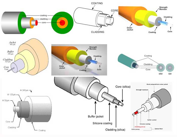
EVERY
fiber drawing we found on the Internet search with one exception
(which we will show in a second) showed the same thing - the
core of the fiber separate sticking out of the cladding and the
cladding sticking out of the primary buffer coating. Those
drawings are not all from websites that you might expect some
technical inaccuracies, several were from fiber or other fiber
optic component manufacturers and one was from a company
specializing in highly technical fiber research equipment.
The only drawing we found that does not show the core separate
from the cladding was, no surprise, on the FOA
Guide page on optical fiber.
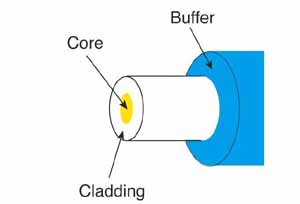
No wonder everyone is confused. Practically every drawing shows
the core and cladding being separate elements in an optical
fiber.
So how did FOA help this student explain the facts to his
instructors? We thought about talking about how fiber is
manufactured by drawing fiber from a solid glass preform with
the same index profile as the final fiber. But we figured a
simpler way to explain the fiber core and cladding is one solid
piece of glass was to look at a completed connector or a fusion
splice.
We started with a video microscope view of the end of a
connector being inspected for cleaning.
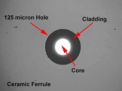
Here you can see the fiber in the ceramic ferrule. The hole of
the connector is ~125 microns diameter (usually a micron or two
bigger to allow the fiber to fit in the ferrule with some
adhesive easily.) The illuminated core shows how the cladding
traps light in the core but carries little or no light itself.
This does not look like the cladding was stripped, does it?
Here is the same view with a singlemode fiber at higher
magnification.
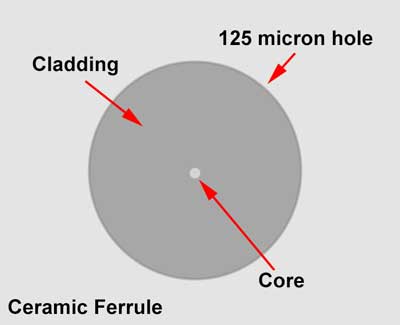
And no connector ferrules have 50, 62.5 or 9 micron holes so
that just the core would fit in the ferrule, do they?
What about stripping fiber for fusion splicing. Here is the view
of fiber in an EasySplicer ready to splice.
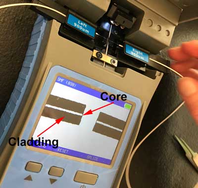
What do you see in the EasySplicer screen? Isn't that the core
in the middle and the cladding around it? In fact, isn't this a
"cladding alignment" splicer?
We rest our case. If that's not sufficient to convince everyone
that you do not strip the cladding when preparing fiber for
termination or splicing, we're not sure what is.
Special Request: To everyone in the fiber optic industry
who has a website with a drawing on it that shows the core
of optical fiber separate from the cladding, can you please
change the drawing or at the very least add a few words to
tell readers that in glass optical fiber the core and
cladding are all part of one strand of glass and when you
strip fiber, you strip the primary buffer coating down to
the 125 micron OD of the cladding?
Termination/Splicing
MM Splice-on Connector On Singlemode Cable
Q: I encountered a situation where a MM
mechanical connector was used on a SM fiber and passed on an OTDR test.
The client and I are interested in understanding how these connectors
could have passed?
A: The joint between a multimode and
singlemode fiber should have vrey high loss, ~17-20 dB, depending on the
mode fill of the MM fiber. However the short length of the MM fiber,
~10mm, might not be enough to cause the modes to fill in the short fiber
in the connector, resulting in relatively low loss.
Eric Pearson, one of the most knowledgeable people on connectors
expressed this idea then tested it with 100m singlemode connected to a
second singlemode cable. The second singlemode cable has an OM3 LC
unicam connector, An EXFO ftb-400 OTDR indicates a 2.09 dB drop. That is
way too much to pass a test but nowhere near the loss that could be
expected from the MM/SM joint. See the OTDR trace below.
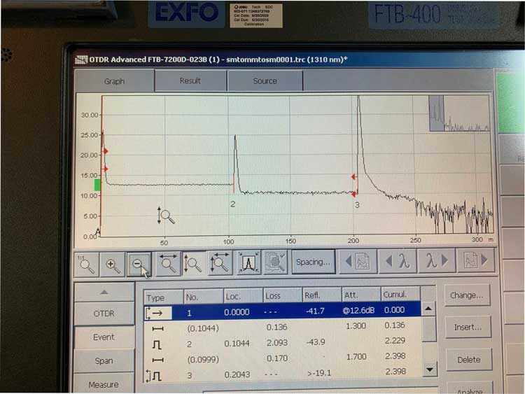
Connector Mating
Adapter Loss
Q: When looking in data sheets on duplex
adapters, it’s telling me that it has a Insertion
Loss of about 0,2dB. Is that common? Only thought it
was the connector that had a loss.
A: Technically,
a single connector or mating adapter does not have
any loss. It’s not “connector loss” but “connection
loss” defined as the insertion loss when two
connectors are mated, and for most connectors that
requires a 3rd component, a mating adapter to align
the ferrules. (Some connectors like MPOs have their
own alignment mechanism so the mating adapter merely
holds the two connectors - one with pins and one
with holes - together.)
The connector manufacturer’s specification for
“Connector loss” is the loss of their connector
mating to a reference connector with a mating
adapter. Connectors are graded in ISO/IEC standards,
but not TIA, and the best connectors are ~0.2dB loss
when mated to another of the same grade.
If a mating adapter manufacturer is quoting loss,
one assumes they mean their adapter with two of the
best connectors will have a connection loss of
0.2dB.
Mating adapters for 2.5mm ferrule connectors - FC,
SC and ST - have a split sleeve alignment bushing
that is the critical element. They have been made
with molded glass-filled plastic, phosphor bronze
and ceramic. In our opinion/experience, the plastic
ones are only good for multimode fiber and wear out
in ~10 insertions, discoloring connector ferrules
and leaving dust scraped off the plastic on the
ferrule ends. The metal ones are good for SM or MM
and hundreds of insertions, but they tend to wear
and leave marks on the ceramic ferrules. The ceramic
ones are recommended for SM and for testing as they
work best and last practically forever.
Maximum Fusion Splice Loss
Q: We have set 0.4 dB as our max for all losses per splice
and my counterparts argue that customer quality will not suffer with a
1.0db-1.5db loss at a splice. What do you think?
A: We would argue that the issue with high loss splices is more
one of reliability. Most fusion splices of singlemode fiber are 0.05 to
0.1 dB A splice that has more than ~0.2dB loss probably has some
inclusion (dirt that got on the fiber after cleaving) or an air bubble
with means the splice is deficient in strength and may fail over time.
If the network is operating at high power with WDM and fiber amplifiers,
the inclusions or bubbles may produce heat which can cause failures. At
very high speeds or using coherent communications over long lengths, it
might affect dispersion.
Loss
For APC vs UPC Connectors
Q:
I was wondering if there will be a standard connector loss for
a UPC connector and a different lower value for an APC
connector.. ex. upc has 0.5dB while APC is 0.3dB.
I would like to make all connectors uniform on a new network
infra to avoid mismatch and causing any possible damage on the
equipment when APC will be plugged into to a flat.
A: There is really no statistical difference between
APC and UPC connector loss. The lower reflectance of the APC
actually reduces loss since the reflectance represents a
factor in connection loss, This issue of connector grades has
been discussed at international standards committees for
years. ISO/IEC wants to have grades of connectors, rated for
connector loss in ranges from 0.1 to 1dB, but I do not think
it’s standardized. I recommend using 0.3-0.5dB for loss
budgets, where in OSP networks it matters little, since there
are only a few connections and fiber and splice loss is a
larger factor.
Keeping UPC and APC connectors straight is easy - APCs are
Green, UPCs are blue. Everybody just needs to be taught that!
Fusion
Splice-On Connectors (SOCs) (From an FOA Instructor)
Q: A
question came up from one of our students regarding splice on
connectors. Is there a TIA or other standards body that
addresses this issue? We are used to the 0.75 dB loss for a
mated pair, however, when this mated pair has two fusion
splices that terminate the connector, is there a
recommendation?
One could make the argument that it does not make any
difference as the other alternative is splicing a pigtail for
termination of a cable. This pigtail splice is normally
included in the link loss budget calculation. So
similarly, with a splice on connector it is the same as
splicing on a pigtail.
A: There are no specific TIA or IEC specs that address
these splice-on connectors or pigtails. If you used TIA
numbers and included the splice and connector it would be
1.05dB - 0.75dB for the connection and 0.3dB for the splice,
that’s mated to a factory adhesive/polish
connector. Or if it were two similar connectors,
1.35dB.
Everybody, including the people in TIA standards groups, know
those numbers are too high for most single ferrule connectors.
They keep them at 0.75dB for prepolished/splice connectors (w/
mechanical splices) and array connectors (MPOs) which have
somewhat unpredictable performance. Internationally, IEC has
created grades of connectors from ~0.3 to over 1dB. The newer
mechanical splice connector kits now use the Chinese copied
cleavers which are super - at least the few we have tested -
and the connectors are now much lower loss and consistent.
SOCs (fusion splice-on connectors) are spec’ed as the total
termination and are generally just as good as the typical
adhesive polish connector - 0.5dB is plenty of margin for a
those mated to a factory adhesive/polish connector.
Spliced on pigtails are generally considered a termination and
the splice is not broken out - like a long SOC. But I cannot
guarantee everybody thinks that way. But a fusion splice is
typically <0.1dB anyway.
APC or
UPC?
Q: Can my otdr test upc connectors? Can I test
this distribution without problems?
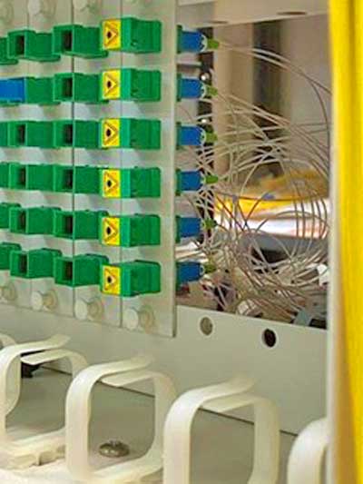
A: APC and UPC connectors are not compatible. APCs are
green, UPCs are blue. See https://foa.org/tech/ColCodes.htm To
test UPC connectors you would need a launch cable that is UPC
on the OTDR end and APC to to mate to an APC connectors. But
if I look behind these green APC mating adapters, I seem to
see blue connectors - blue is UPC not APC. (add photo)
APC
Connectors
Q:
We've got a discussion going in our department about
whether an APC connection is required at both ends of an
electronics link or just in one spot when trying to control
reflection for broadcast equipment. Thoughts/advice?
A: It seems you could use APCs on the transmit end to
prevent reflectance bothering the laser source, but it would
get reflectance from the receiver end, probably not an issue
unless you are on short links, like in a data center where the
far end reflectance would not be attenuated
substantially. If you put the APC at the receiver end,
you would still have problems with reflectance at the
transmitter end. Perhaps the biggest problem is managing to
keep patchcords straight. We’d vote for the simple solution,
all APCs, which is what many people are doing today.
Alternatively, use the best UPC connectors which have only
about 10dB worse performance as long as they are kept clean.
PON
Troubleshooting
Q: I have question about DBM IN GPON system with
splitter 1:64. I spliced 2 fiber from splitter to customer
going through 4 splicing points and when I measured the loss
at the end (customer) the #2 fiber was fine but the #1
fiber was down 12 dB. I checked the fiber with OTDR without
splitter and it looks fine. What you think is the problem?
A: You need to test the splitter itself to make sure
all ports are good.
Testing
Pigtails
Q:
A customer said he said he would test 100 foot pigtails with
OTDR. I question that practice and think OLTS Tier 1 and
microscope test for defects,
A:
Pigtails do not have a connector on one end so that makes OTDR
testing more justifiable. Clean connector, mate to connector on
long reference cable, check connection and length. OLTS testing
would require using bare fiber adapter or temporary splice and
might not be very accurate.
Splice
Loss
Q:
We are installing 216 fiber aerial cable for 12km with 2
splicing points. We use 3 different fusion machines and they
report that all splices are 0.00db. But when we check using
OTDR we get above 0.04db. The question is how can we get below
0.04db splicing loss?
A: The loss results from both fusion splicers and
OTDRs are estimates, with considerable uncertainty. The
splicing machines estimate based on the optical images of the
fibers. The OTDR estimates loss based on fiber backscatter and
may give significant differences depending on the direction of
test. The differences you quote are within the uncertainty of
the two instruments.
APC
Connectors
Q: Why NOT make the use of APC connectors the new
standard for all adds, moves and changes to any campus, MDU or
similar application using single mode cable?
A: There is absolutely no reason not to use APC
connectors other than the cost is slightly higher and one must
be careful if they are used in a cable plant that also has PC
or UPC connectors because they are incompatible. We recommend
them all the time for short links like data centers, passive
optical LANs and FTTH where runs of singlemode fiber are
short. In fact they are very common in these networks today.
Cleaning
Connector Protective Caps
Q:How do you clean LC Fiber Optic end caps (the cap that
covers the cleaned fiber cable)? Is there a tool for that?
A: We assume you are talking about the small plastic
protective caps on the connector ferrule. There is a joke in
the industry that goes “there’s a reason they call them "dust
caps’” they’re often full of dust.” The problem is these are
plastic molded parts that are made by the billions for various
purposes - some just fit fiber optic connectors. They come out
of the molding machine and are dumped in barrels. No provision
is made to keep them clean, plus they will have some mold
release chemicals inside them that can attract or hold dust.
Even static electricity is a problem.
We know no way to clean them nor to keep them clean. We
recommend using them to protect the connector ferrule - in
fact we’re trying to get people to call them “protective caps”
- but after they are removed and before use (connecting to
another cable or a transceiver or testing them) they need
inspection and cleaning.
See these pages in the FOA Guide: Microscope
Inspection And Cleaning of Fiber Optic Connectors
Cleaning
Fiber Optic Connections
Directional Splice Loss
Q:
I have a customer that is splicing a fiber distribution hub to
their fiber plant. The fiber distribution hub utilizes
100FT long fiber stubs of SMF G.657.A1 and the fiber plant
uses SMF G.654.D. The project has a contract fusion
splice passing spec of 0.2dB loss, averaged bi-directional and
also a one-way <0.3dB loss (either direction)
specification; using an OTDR for measurements.
From my research, if the splices OTDR’s test results for the 2
directions are -0.2dB / +0.6 (average of +0.2), the network is
not actually seeing a +0.6dB loss; but this is how the OTDR
interprets the backscatter information… the OTDR being
somewhat confused due to the bend insensitive fiber
characteristics.
A: Correct - the directional differences are due to the
mode field diameter variations in the two fibers. G.654
is a large MFD fiber, ~12.5microns, compared to ~9 microns for
G.657.A fiber. The OTDR measures based on backscatter which
will be very different for the two fibers.
Connector
Mating Adapters
Q: I am looking for a standard that describes the value
of parameters (IL, RL) and class (if we can talk about class)
for FO mating adapters.
A: Mating adapters are part of the connection but like
each connector they only contribute to the total loss of the
connection and cannot be separated from the other two when
talking about loss. They can be specified by mechanical
dimensions and materials. For example on 2.5mm ferrule
connectors (SC, ST, FC and the obsolete FDDI and ESCON duplex
connectors) the mating adapters have had alignment sleeves
made of molded glass-filled thermoplastic, phosphor-bronze and
ceramic. The plastic ones are cheap but wear out quickly - 10
insertions will leave plastic dust all over the mating
connectors. Phosphor-bronze mating adapters last longer -
maybe 500 cycles. The ceramic sleeve ones last almost
indefinitely. We know this because we were in the test
equipment business for 20 years (we started FOTEC in 1980 and
sold it to Fluke in 2000) and we tested these mating adapters
for longevity with reference test cables used in insertion
loss testing. We had many calls from techs with problems
caused by the adapters with plastic sleeves. So the way we
know the mating adapters are graded is by alignment sleeve
materials.
APC
Connectors
Q: With a fiber optic pathway that has multiple
patching points...if the end user requires APC connections,
isn't it only important to have those angled connectors at the
end/equipment connections with UPC being acceptable throughout
the middle part of the link?
A:
Reflectance at the connection is the issue, of
course.
Reflectance near a transmitter can affect the laser
transmitter causing nonlinearities or noise in the device.
That’s always been a major concern.
The second issue is reflectance causing background noise in
the link. If you have ever seen a ghost on an OTDR, you have
seen a reflectance at a connection that is bouncing back and
forth in the fiber and is of high enough amplitude that you
can see it at the source. Of course if it reflects back and
forth in the fiber link, it will also show up at the receiver
end, becoming noise and/or distorting the receiver pulses. In
a bidirectional single-fiber network like a PON, it affects
receivers at both ends.
Some refer to this as multipath interference. It is being
studied by international standards groups but nothing has been
published on it as far as I know.
We are familiar with a link that was ~1km of SM fiber with
hand-polished ST connectors at several connections. The link
had acceptable loss for all the fibers in the cable but none
would work with electronics. Replacing the connectors with
fusion spliced pigtails cleared the problem up immediately.
Was the problem
With that background, I would answer you question this way.
APC connections at each end of the link will effectively stop
any reflectance issues going back and forth in the whole link.
Using UPC or PC connectors in the link with reflectance better
than -40dB are unlikely to cause problems. (Keep them clean of
course since dirty connectors show high reflectance.) If the
links are very short (<1km), the fiber will not attenuate
any reflectance substantially, so short SM links (FTTH and
passive OLANS for example) often use APC connectors
everywhere.
And a final practical issue - mixing APCs and PC connectors is
very bad, perhaps damaging the surfaces. If you do mix them in
a link, you must train personnel how to handle them. If you
have patch panels with PCs and equipment with APCs, for
example, you have to ensure the patch cords are color coded
properly (blue = PC, green = APC) and everybody knows not to
mix them
Connector
Loss At Patch Panel
Q: If I have two SC connections in a cabinet eg one
incoming cable jumperd to an out going cable. Should I be
looking for a loss of no more than .75db across the two of
them as per TIA-568
A:
TIA 568 has included a connector loss of 0.75dB for decades.
Even the committee is aware that this is a bogus number for
most connectors but they leave it in because the manufacturers
of MPO connectors need it to comply with the standard.
SC connections should be ~0.2-0.3dB if the connectors are good
and properly cleaned. Now in the patch panel you describe,
each of the two connections should be in that range for a
total loss of 0.2-0.6dB. TIA would allow 0.75dB for each
connection or 1.5dB total.
Differences
Between Singlemode or Multimode Connector Mating Adapters
Q: What is the difference between singlemode and
multimode bulkhead/adapters (mating adapters). My
understanding is you cannot use the singlemode with the
multimode and visa versa.
A: There are 3 types of adapters - rated for SM or MM
- based on the alignment sleeve material.
-Plastic (glass filled thermoplastic) alignment sleeves are
cheap, not very precise and wear quickly (you can see ceramic
ferrules get dirty using them) - only good for multimode and
one or two insertions - not recommended
-Metal (phosphor bronze) alignment sleeves are better with
good alignment but still wear some - OK for MM, some are rated
for singlemode (check before you buy), and are OK for most
uses but will wear out if used for repetitive testing
-Ceramic alignment sleeves are the best and most expensive.
They are very precise in alignment and last for a long time.
Recommended for all singlemode and all testing purposes.
Don’t use MM adapters for SM but SM adapters are OK for MM.
Polishing
Films
Q: Are there different grades (micron)
polishing films/papers for multimode and single mode fiber
cables in ODF termination ? If yes, What are the grades
polishing papers for multimode 50/125 um and 62.5/125 um
fibers.
A: The polishing of
MM and SM fiber is indeed different. Both start with an “air
polish” with 12micron alumina polishing film to remove the
protruding fiber. Then the polishing continues on a soft
polishing pad (3mm 80 durometer rubber).
MM uses a 3micron alumina polishing film polished dry then a
final 0.3micron alumina film polish. See
http://www.thefoa.org/tech/ref/termination/ConnHints.html
SM is usually done with a wet polish using as special
polishing slurry and diamond polishing film. The diamond film
will polish both the ferrule and the fiber to get the best end
finish. See http://www.thefoa.org/tech/ref/termination/sm.html
There are even more pages of information on the FOA Guide at http://www.thefoa.org/tech/ref/contents.html#Components
MPO
Connector Loss
Q: Is there a current standard, for maximum allowable
loss, for MPO fiber connectors? If so… what is the standard #
from EIA/TIA? (Was it amended in 568B, since they were
introduced?) Would it be similar to standard connectors @
0.75dB Max allowable loss?
A: The MPO is covered
under the TIA 568 standard. All fiber optic connectors are the
same - 0.75dB.
There are discussions being held at TIA and ISO/IEC on using a
different method of specification, statistical in nature, that
says X% would be less than YdB in several stages from 0.1-0.2
to over 1dB, but it’s led to some headed discussions.
MPOs for MM are probably no less than 0.5dB and SM are near
the 0.75dB mark. At least the SM ones are APC (usual 8
degrees, but still a flat polish).
I’ve recently learned that MPOs are polished for fiber
protrusion to try to get fiber contact, but the evenness along
the line of fibers is harder to control.
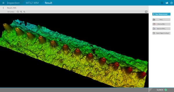
image from SUMIX
showing protruding fibers in MPO connector
Fusion Splicing Regular And Bend-Insensitive
Singlemode Fiber
Q: Would fusion splicing
single mode bend insensitive to standard fiber with
same core cause a numerical aperture mismatch? We
are seeing loss but it’s hard to tell from what.
Going from a drop to BI inside cabling. Any
direction is appreciated!
A: There is a lot of
controversy in this area and has been for some time.
The issue is mode field diameter(MFD)
differences between regular and bend-insensitive
(BI) fiber caused by the low index trenches around
the core that are used to limit bend insensitivity.
Some (maybe most) manufacturers make BI SMF to match
MFD of their regular SMF, since a common use is
splicing BI SMF pigtails onto regular SMF. With so
much BI SMF fiber being used in microcables and high
fiber count cables, the opposite situation could be
an issue also.
Another factor at play here is the fusion splicing
program. The different structures of the fiber may
need special programming in the fusion splicer to
get heat and feed right for the two different
fibers.
FOA hopes to have some independent data on this
topic soon. FOA Master Instructor Joe Botha has done
tests before on splicing dissimilar fibers when BI
fiber first became available (read the
report here) and has planned a
more extensive set of tests to update that data for
more recent fibers soon.
Fusion
Splicing Live Fibers
Q: Is it safe to fusion splice a live fiber, or is
there a chance that
the light from the arc will damage the detectors in the
modules at the end (20km-rated SM for us).
A: I have never heard
of this being a problem. The amount of light coupled into the
fiber from the splicing would be very small compared to a
properly coupled laser. When a cable is broken you might be
splicing the fibers that are live without knowing which are
live and not caring. On your newer splicers this is not a
problem. On the older splicers with the LID system you would
have to reduce the power to get a good splice which they would
do by putting a bend in the Fiber.
Maximum Fusion Splice Loss
Q: We have set 0.4 dB as our max for all losses per splice
and my counterparts argue that customer quality will not suffer with a
1.0db-1.5db loss at a splice. What do you think?
A: We would argue that the issue with high loss splices is more
one of reliability. Most fusion splices of singlemode fiber are 0.05 to
0.1 dB A splice that has more than ~0.2dB loss probably has some
inclusion (dirt that got on the fiber after cleaving) or an air bubble
with means the splice is deficient in strength and may fail over time.
If the network is operating at high power with WDM and fiber amplifiers,
the inclusions or bubbles may produce heat which can cause failures. At
very high speeds or using coherent communications over long lengths, it
might affect dispersion.
How
Long Does Termination Take?
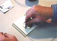
FOA received a request from a consultant recently wondering if
we had information on the termination times for fiber optic
cables. After some looking in our archives, we realized we had a
document online that compared times for various fiber optic
termination processes. The paper was written after several FOA
instructors did a comprehensive time and motion study on
termination processes. The document is about 15 years old but
still relevant.
You
can read it here in the FOA Online Guide.
Testing
Connectors (From A Patchcord Maker)
Q: What are the chief defining standard(s) that
specifies connector and assembly IL (insertion loss) and RL
(return loss or reflectance) for both SM and MM fiber?
A: The description on
our Guide is here: http://www.thefoa.org/tech/ref/testing/test/conntest.html
FOTP-34 covers connector testing as a qualification test
for the type of connector - basically a "destructive" test for
connector manufacturers.
Reflectance is described on that page and here also: http://www.thefoa.org/tech/ref/testing/test/reflectance.html
Testing an assembly like a patchcord is covered under
FOTP-107 http://www.thefoa.org/tech/ref/testing/test/FOTP-171.html
"Connector
Loss" or "Connection Loss"
Q: I have always counted the loss of a connector as
.75 dB (568B-3) and 1.5 for a mated pair. Is that correct?
A: While the industry
always says "connector" loss, it is actually "connection"
loss. As we explain in the page on termination and splicing (http://www.thefoa.org/tech/ref/basic/term.html)
When we say "connector" loss, we really mean "connection" loss
- the loss of a mated pair of connectors, expressed in "dB."
Thus, testing connectors requires mating them to reference
connectors which must be high quality connectors themselves to
not adversely affect the measured loss when mated to an
unknown connector. This is an important point often not fully
explained. In order to measure the loss of the
connectors you must mate them to a similar, known good,
connector. When a connector being tested is mated to several
different connectors, it may have different losses, because
those losses are dependent on the reference connector it is
mated to."
The TIA spec of 0.75dB is for a mated pair of connectors. If
you have been passing connectors tested @ 1.5dB loss....you
may have some very bad connectors in your cabling!
Test
& Measurement
OTDR
questions are the most common questions on testing so they
have their own section below.
Basic
Tests For Fiber Optic Cable Plants
Q: I did some research and I noticed that there is a
bunch of tests that can be done to fiber optics and I was
wondering if there is a list of primary tests that can be done
as a basic test.
A: Fiber optic testing
does have a hierarchy of tests.
- At
the top of the list is "insertion loss" testing which uses a
light source and power meter to test the fibers in the
same way that a communications system transmits over the
fiber. It is a simple test and the equipment needed is
inexpensive.
- Techs
will also use a microscope to inspect the fiber optic
connectors for dirt and damage, a big issue for fiber.
- The
instrument called an "OTDR" takes a snapshot of the fiber
using a technique like radar. Most outside plant cables are
tested with an OTDR and the data ( the snapshots are called
"traces") stored for future reference. OTDRs are more
expensive and require more training to use properly.
Here is a
link to a page on the FOA Guide site that explains the
technical,details: http://thefoa.org/tech/ref/testing/test/OFSTP-14.html
FOA also has information just for users of fiber optic networks,
see http://thefoa.org/tech/guides/UG3.pdf
Is A "Flashlight Test" Adequate?
Q:
I contracted a firm to install an OM3 of 200 meters.
On one end I have an SFP 1000SX ,on the other a 1000SX
converter from optical to UTP. We made pings but they never
reached, and I didn’t see the laser at the extreme of the
fiber. They promised me to send me the certification they
supposely made ,though they assured me the fiber is ok,
because WITH A FLASHLIGHT THEY SENT WHITE LIGHT FROM ONE
SIDE TO THE OTHER AND IT WAS VISIBLE. I saw the light too, and
I thought the culprit was my switch or my SFP. I want to know:
is this a good demonstration that the fiber is ok?
A: A visual
continuity test is not adequate - your eye is not calibrated!
The power of the lamp is unimportant as each eye’s sensitivity
is different. And your eye probably cannot see the light from
a 850nm VCSEL source - most people’s eyes are not sensitive at
that infrared wavelength. The installer should have tested the
link with a light source and power meter (http://www.thefoa.org/tech/ref/testing/test/OFSTP-14.html)
and given you the loss in dB. The connectors should also be
inspected with a microscope to ensure proper polishing and
cleanliness
(http://www.thefoa.org/tech/ref/testing/test/scope.html). If
the SFP output is -6dBm, what is the power at the receiver?
1000base-SX is supposed to work with 4.5dB loss (see
http://www.thefoa.org/tech/Linkspec.htm). The fiber loss
should be ~0.6 dB, so you must have >4dB connector losses!
That says bad installation! The 1000SX link should work over
200m if the fiber has been properly installed.
Using A Visual fault lOcator
Q: What are the best practices for using a VFL to locate fiber faults?
A: See https://foa.org/tech/ref/testing/test/visual.html in the FOA Online Guide
Microscope
Magnification (11/13)
Q: I am doing a lot of
fiber optic jumpers for control systems, either single
mode or multimode. I want to get a scope to inspect the ends
after I clean them would you recommend a 200X, 400X
handheld or one similar to a Noyes OFS 300 200C?
A: We prefer to use lower magnification and have a wider
view so I can see more of the ferrule to determine its
condition. You can see the fiber effectively at 100X but 200X
may be better. 400X may be too much for most tasks like
inspecting for cleanliness, but may be good if you are polishing
SM for good reflectance. We've used the Westover units for years
because they offer two different methods of illumination -
direct and at an angle. If you are doing a lot of patchcords, I
recommend a video microscope. I've used the Noyes unit that
interfaces to a PC to create the FOA Microscope Inspection
YouTube video here: http://www.youtube.com/watch?v=IyumH8CiUPQ&feature=youtu.be
and it works well.
Calibration of Fiber Optic Power Meters
Q: Why does this tester sold so cheap show the same value for 1310 and 1550?
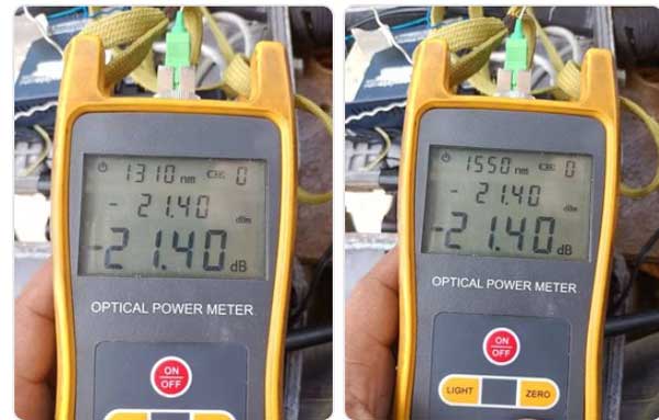
A: We’ve purchased and tested several
of these inexpensive meters based on questions from our instructors and
readers. They have a similar “feature” - they are not calibrated to
international standards of optical power, so when you measure dBm, the
result at any wavelength may vary considerably from a meter by a major
manufacturer who does calibrate properly.
However, these meters have a menu item that allows you to calibrate them
yourself. We've calibrated all the ones we tested to match our
calibrated instruments and after that they work OK.
Interestingly, they show loss as negative dB, which is how we think it
should be. Some large, famous manufacturers manipulated the standards to
make loss a positive number, so if you measure gain, it is considered a
fault.
Differences in OTDR Traces
Q: What causes the differences in otdr traces for fibre cores that are in the same cable?
A: Several things can cause the fibers in a cable to have differences in their OTDR traces:
Differences in fiber from different production batches including fiber that may come from different preforms.
Differences in stress on the fiber caused by inconsistent cable design and manufacture
Of course differences in splices including stress on fibers in a splice
closure and terminations including stress on fibers in racks and panels.
Test Source Variations
Q: When we plug in the patch cable to use as a reference
to get ready for our insertion loss test, our power meter gives us
different readings each time we plug in and unplug the cable. Is
this normal?
A: If you plug a reference cable into a source, it is likely
to have some variation in coupling each time so the power out of the
cable is different. Once you plug the cable into the source and a
reference set with the meter, you should not remove the cable until you
finish testing.
Test Source Modulation Options
Q: Our light source user’s manual listed the following:
“In the actual project, it is necessary to load the audio carrier in the
optical signal to identify the optical fiber. The equipment contains
three carrier frequencies, which are 270Hz, 1KHZ, and 2KHz.” Can you
tell me if I need to be concerned about setting this to a certain value?
A: Sources often have an option to modulate the source for
use with another instrument called a “fiber identifier.” Then it offers
the output as DC or CW (a steady unvarying signal) or modulated at
270HZ,1 or 2 kHz. When testing loss the DC or CW setting should be used.
850 LED Test Source
Q: I need to test multimode fiber at 850 nm but sources are hard to find and expensive. Can I use a laser?
A: Multimode
fibers should be tested with an LED. Lasers have several problems in
multimode fiber that may cause untrustworthy readings. The problem is
that LEDs are no longer used for transmission systems; every MM system
now uses VCSEL transmitters, a surface emitting laser. As a result most
LEDs at 850nm for MM have gone out of production. Two engineers I know
who have been looking for them say there is now only a few sources and
the price is much higher that of a few years ago. We've been buying used
test sources on eBay for training.
Optical Power Of FTTH Signals
Q: I wanted to know on a fiber to home what is the optimal signal
strength I should receve at? I have a leg that is 21 km long I
receive at 1490 at -22 dBm is that to low, everything looks good on my
traces
A: The specifications for GPON are here. https://foa.org/tech/ref/appln/FTTH-PON.html
The standard for GPON calls for receiver power at -13dBm max to -28dBm minimum, so -22 dBm is OK.
Documenting Fiber Optic Cable Plants
Q: I am looking for information or
training materials on documentation standards for OSP cable. We
currently have a number of large backbone cables along with mid span
cables. I know companies like the phone company labels each cable
with a number and terminals off of the mid span drop with the specific
pair numbers. Is there a standard way to label each cable, mid
span cable, splice box, terminal, etc.?
A: The usual way is to document every
fiber in every cable with a fiber designation, color code and
connections on each end. There are some standards on numbering schemes
but most companies I know use their own designations created as they got
started. There are software packages that will do this work,
simplifying the process,
Documenting Test Results
Q: We’re currently working on a bid that
includes presenting some test sheet documentation for OTDR &
Light loss testing. What should I do?
A: High end LSPM or OLTS should store data and have some
software to report test results. Simpler units should simply
require logging data into a spreadsheet showing Cable ID, Fiber
ID, wavelength and loss. Details like launch & receive
cables and test results can be kept separately on the
spreadsheet. Today’s OTDRs will show you a trace and an event
table that lists each even in the fiber tested as well as
overall loss. Whatever OTDR you use should have software for
reporting test results. Here is an example of a report from an
EXFO and a trace from a Yokogawa.
Maintaining
Dark Fiber
Q: Do
you have any standards that speak to how often dark fiber should
be tested with OLTS and OTDR? Such as just at installation and
when troubleshooting, or should they be done on a regular basis?
A: We at FOA know of no standards calling for periodic
testing of fiber optic cable plants.
Fiber optic networks generally do not require maintenance and it
is often detrimental to the network. It is the opinion of FOA
and most people in the industry that testing should be done upon
completion of the installation and data submitted to confirm
proper installation of the cable plant. Data should then be
stored for reference in case of problems requiring
troubleshooting or when new dark fibers are turned up. Before
lighting a dark fiber, it should be tested and the results
compared to earlier data. Since both tests have some
uncertainty, test results can vary as much as 0.5dB on short
cables, higher on longer runs.
If older fiber is being upgraded to higher speeds, now cities
like Santa Monica where we live are upgrading to 100G networks,
fiber characterization including chromatic dispersion,
polarization mode dispersion and spectral attenuation (for DWDM)
are advised. Of course, every time a connection is opened, it
should be inspected and cleaned. And patchcords should be
tested; even new ones in sealed packages are often dirty. There
is a reason people call the plastic protective caps on
connectors “dust caps!”
Otherwise, with fiber, we suggest the patch panels be locket to
keep unauthorized personnel from accessing them and causing
problems. Even disconnecting a connector can add dirt to the
connections and cause problems.
Identifying
Users On A PON Network
Q: How or what testing tool or
technique can I use to verify whether there is a live customer
w/ONT working on any fiber i may select @ a splice enclosure
prior to getting further down the cable and to the MST
service terminal. All our fibers have light on them leaving the
CO so when we go into a splice enclosure to pick a fiber to
connect a drop to, to service a home, they are usually all lit
up in that enclosure.
A: The simple answer for a tool or technique that can
tell you if a customer is connected on an output of a PON
splitter is “documentation.” If you know where each fiber is
connected going downstream. Then the IT person who programs
users into the system can tell you if that fiber is connected to
a customer. There is a possibility that there is a test
solution. Have you ever heard of a “fiber identifier”? It’s a
gadget that can tell if there is signal in a fiber and some can
identify the direction it comes from. What I don’t know if the
unit can somehow indicate bi-directional traffic. Nobody we
contacted seems to know either.
Microscope
Power For Connector Inspection
Q: What
power microscope do you recommend to inspect
singlemode/multimode in 1.25/2.5 format (ST, SC, LC)?
A: Microscopes in the range of 100-400 power are
available. Many people assume higher power is best - and it is
for examining polishing results in the center of the ferrule -
but lower power helps inspect more of the ferrule for dirt when
used in the field before connecting or testing cables. We prefer
the lower power.
So for patchcord manufacturers, 400, field techs 100. Patchcord
manufacturers will undoubtedly use video microscopes, most field
tech the optical ones.
Power
Budget For PON
Q: Do you have any information on guidelines for
avoiding over saturation in a PON network? Our ONTs have a
power window of between -8dBm and -27dBm. OLT
transceivers transmit at around 4dBm. So our designers
budget for no more than 28dB of loss. However, some ignore the
-8dBm maximum power spec. With a short run from OLT to
ONT and a small splitter, installers are sometimes seeing
light levels at the ONT at around -6 to -7dBm. What would you
recommend as a minimum loss budget in this case? Do we
need margin?
A: The GPON spec does have a max power at the ONT
generally expressed as a minimum loss in the cable plant -
13dB for GPON. There is a graph about halfway down this page
(https://foa.org/tech/ref/appln/datalink.html) that shows a
graph of BER vs Receiver power. To have a link work properly,
it must have sufficient power to be above the minimum S/N -
signal to noise - ratio for the link but not so much power
that it saturates the receiver.
This is a very common situation in telco networks where links
are designed for relatively long distances but may be used on
short ones - e.g. a 40km link being used over 10km in a city.
Their solution is simple - add an attenuator
(https://foa.org/tech/ref/appln/attenuators.html). Lots of
these links use attenuators.
In a PON, there are several ways to go. 1) Brute force - test
each ONT and add attenuators as needed. Techs could carry a
selection of 5dB or 10dB attenuators to get at least to the
13dB minimum needed. 2) Rather than require testing at each
ONT, have the designer do a loss budget based on the link
length and specify a minimum splitter in the link (8:1 would
probably work well) which would probably be cheaper than
testing and adding lots of attenuators.
VFL
Works On Multimode And Singlemode
Q: Will a VFL for single mode work with a multi mode as
well?
A: Yes, a VFL works for either SM or MM fiber. Tight
buffer MM is no problem. On patchcords, the ability to see
light through the jacket of the cable depends on the color and
transparency of the plastic. On buffered fiber, it works well
on most 900 micron buffer fibers.
Troubleshooting
Links
Q: I have a run of 12 Strand single mode fiber from a
remote closet back to my main equipment room. I
unpluged it this morning to check another cable and when i
plugged it back i have lost communication with the remote
closet. Can you help me with some trouble shooting
ideas. I have already tried a new cable from the
termination point back to the switch but still no
communication.
A: The first guess is that the fibers are not
connected correctly - transmitter to receiver. That’s the
first thing to check. The second possibility is dirt on the
connector or in the connector housing on the transmitter or
receiver. Cleaning might be the solution. Third and worst
possibility is the connector was damaged when being
disconnected.
Q2: I ended up powering down the switch in the
remote closet and plugging the fiber in then powering it
back up and it picked up communication again. Strange
??
A: Nope, makes sense. Many new networks shut down
unless they have full duplex communications. If the link is
broken, it shuts down until reset.
Testing Samples Not Everything
Q: Instead of testing everything, how does one determine
how many fibers or components to test for a reasonable
statistical sampling?
A: The relevant term is AQL - acceptance quality limit
- a term that is used for statistical sampling for testing.
Here is a web page that explains it:
https://qualityinspection.org/what-is-the-aql/. Let testing
and inspection evolve. At first test thoroughly, but drop
testing anything that never fails, it’s a waste of time.
Qualify vendors and test trusted vendors less.
GPON
Power Test
Q What is normal Range for good power in an FTTH fiber?
A: The GPON specification for downstream power from the
OLT is OLT transmitter power should be 0 to +6dBm and link
attenuation in the range of 13 to 28dB, which says receiver
power the ONT must be a maximum of 13 dB less than +6dBm or
-7dBm and a minimum of 28 dB less than 0dBm or -28dBm, so -7
to -28dBm at the receiver.
Upstream, the similar calculation is ONT transmitter -4 to
+2dBm and the receive power at theOLT is -11 to
-32dBm.
See http://thefoa.org/tech/ref/appln/FTTH-PON.html for the
full specifications for GPON.
Testing
Cable Before Installation
Q:
Does the FOA publish a standard for assessing
single-mode fiber optic cables, prior to use on a specific
project?
A: The ANSI/NECA/FOA-301 fiber optic installation
standard covers this in Section 4.1. It recommends visual
inspection and testing if there is any suspicion of damage to
the cable. Many contractors will test a couple of fibers with
an OTDR before installing any cable, just for assurance. It
requires an OTDR with a pigtail launch cable and a mechanical
splice.
Test
Multimode At 1310nm?
Q: Can I test multimode over 1310 wavelength?
A: Certainly you can, but why? In fact, multimode fiber
has been tested at both 850 nm and 1300 nm for most of its
history. Some standards still call for testing at both
wavelengths.
When network speeds were 100Mb/s or less, sources were LEDs at
850nm used for shorter links - a few hundred meters - and LEDs
at 1300nm were used for longer wavelengths, up to 2km for
networks like Ethernet, FDDI and ESCON.
When Ethernet jumped to 1 gigabit/s, LEDs could not be used;
they were limited to ~200 Mb/s. The new fast VCSEL sources
(vertical cavity surface-emitting lasers) were adopted for
most links. Some networks still offered a 1300 nm option using
1310 nm Fabry-Perot lasers since VCSELs are limited to about
950nm wavelength max. The 1310 lasers available were generally
pigtailed with singlemode fiber and required some special
launch cables to prevent modal problems, and even though they
offered longer range, they were not really cheaper than using
singlemode fiber and never gained much popularity. (See
Specifications for fiber optic links and systems, including
FTTx)
So multimode fiber became almost exclusively used at 850nm. In
standards committees we discussed dropping the requirement for
testing at 1300nm, but some argued that since the fiber is
more sensitive to stress/bending losses at 1300nm, testing at
1300nm provided information on the stress in the fiber. Once
multimode fiber became almost exclusively bend-insensitive
fiber, that argument lost validity.
While some standards still call for 1300nm testing and many
test sets offer 850nm and 1300nm LED sources, it’s probably
not worth the time.
Testing OM2/3/4 Multimode Fiber
Q: Is there any loss concerns when mating an OM2 fiber to an OM4 fiber (vs using the same type only).
The question applies to both use of an LED source and an VCSEL laser
source. We can assume it is only for short fiber lengths (< 25meters)
A: OM2, OM3 and OM4 fibers have the same basic specifications.
Based on this specification, the two fibers are geometrically identical
and there should be no difference between them.
However, about 10 years ago, multimode fiber was introduced with
bend-insensitive structure.
https://foa.org/tech/ref/fiber/BIfiber.html Today almost all
multimode fiber is bend-insensitive. Earlier MM fibers, including the
OM2 fibers, are not bend-insensitive. Unlike SM fiber, where
bend-insensitive singlemode fiber is given an different designation -
G.652 becomes G.657 - multimode fiber is not differentiated between
regular and bend-insensitive, cables are not marked, and it takes a
knowledgeable tech with a microscope to tell the difference.
Until recently, testing standards called for test reference cables to be
non-BI fiber because the early BI fibers simply added a lower index
trench around the core to capture the lost modes which gave them a
larger core diameter and higher effective NA and these fibers did not
respond the same way to traditional mandrel wrap mode filters - in fact
the specified mandrel wrap had virtually no effect at all. When non-BI
fibers were tested with BI fibers, the effective core diameters produced
directional loss effects. Over a decade, MMF manufacturers learned more
about BI fiber structure and modified the index profile of the fiber to
essentially make BI fiber about the same as non-BI fiber. In addition,
mode control was changed to encircled flux controlled sources instead of
mandrel wrap mode filters, which was more effective with both
fibers.
So recently, MM testing standards have changed. You can use whatever 50/125 fiber you have to test OM2, OM3 and OM4 fiber.
Mismatched
Fiber Losses
Q: If
I have 50 micron test leads for my OLTS and I used them to test
a 62.5 micron fiber link what can I expect in terms of
results? Will the 50 micron leads give me (generally)
higher or lower loss values?
A: Yes, you will see higher and or lower loss depending
on which way you test. See this
page in the FOA Guide on Mismatched Fibers.
Reflectance
And Return Loss
Q: Help me understand measuring
reflection little better. Why do we consider -55dB to be a
better reading than, say, -25dB? If reflection and return loss
are inverse readings and we had a 55dB return loss, would that
positive reading for return loss be considered good?
A: Reflectance is measured as the ratio of reflected to
incoming signal at a connection. The confusion comes because
reflectance and return loss are inverse readings. Consider this:
If we have 1/1000 of the light reflected, the reflectance would
be -30 dB (1/1000 = -30 dB) but the return loss would be 30dB
since it is defined as 1000/1, the inverse, and is described as
+30 dB.
Likewise, an APC connector would have a reflectance of -50 dB or
a return loss of 50 dB.
However, return loss as tested by all OTDRs is not be the
reflection from a single event but the total of all reflectance
events plus total backscatter from the length of fiber being
tested in the trace.
This is where most people are confused and misuse the terms.
Reflectance
Q: What is the importance of reflectance and all the other numbers in installing and trouble shooting a fiber circuit?
A: Reflectance has always been a secondary issue to connection
loss but has some important issues that need consideration. There are
two basic issues with reflectance, affecting with the output of laser
transmitters and creating background “noise” in a fiber link.
Reflectance can interact with the laser chip itself, causing laser
transmitters nonlinearities or random fluctuations in the output. The
background noise is a secondary issue, but can be seen in ghosts in an
OTDR trace. The light bouncing back and forth in the fiber that causes
ghosts will be added to the signal at the receiver end, adding noise to
the actual signal. Both these effects are more significant on shorter
links, for example FTTH or LANs using PONs (passive optical networks).
We always recommend using APC (angled physical contact) connectors on
short SM links. And most short SM networks do use APC connectors.
FOA tries to stick to the definition that reflectance is the light
reflected from a connection but some others call it “return loss.”
Return loss has been defined generally as the combination of reflectance
and backscatter from the fiber, and that’s how OTDRs measure return
loss. Standards vary in the definition sometimes.
Here is a FOA Guide page on reflectance that gives the basics and
explains how it is tested.
https://foa.org/tech/ref/testing/test/reflectance.html
Reflectance Testing Expanded Beam Connectors
Q: We have a contract where we are required to
test assemblies that vary from 0.5m to 800m in length with
connectors of either PC to Expanded beam or expanded beam to
expanded beam type.
LC/SC/ST
-----------to------------- MIL-DTL-83526
Or
MIL-DTL-83526 -------to----------
MIL-DTL-83526
We currently have a back reflection ‘power meter’ on loan
but have been told that the results for assemblies above 5m
lengths may not be reliable to measure the connector termination
due to the nature of the expanded beam termination and
cumulative scatter reflection in the cable.
Therefore we are considering OTDR equipment for our back
reflection testing but trials we have done so far show that the
‘standard’ OTDR testers are not able to separate events that
occur within a 1 – 2m length so we are not able to separate
connections on short lengths.
We are coming to the conclusion that we will now need to
purchase both a back reflection meter and OTDR to cover the 0.5m
to 800m range but would appreciate any industry knowledge we can
find.
A: We took some time to try to research
measuring reflectance on expanded beam connectors and was
surprised how little I could find. FOA has a web page
summarizing reflectance testing (http://thefoa.org/tech/ref/testing/test/reflectance.html)
and a full chapter in our book on testing (http://thefoa.org/FOArgTest.html)
but I don’t remember ever being asked about reflectance on
expanded beam connectors.
The best information I have found indicates that reflectance is
fairly high because of all of the optical surfaces. It’s
possible to test all the cables - short to long - by using a
mandrel wrap attenuator after the connectors under test. But if
these are multi-pin connectors with multi-fiber cables, that
won’t work.
Generally OTDRs are not good for short length testing but
fortunately there are specialized instruments designed for your
application. Here is the Luciol OTDR from Switzerland which can
do the job (http://www.amstechnologies.com/fileadmin/amsmedia/downloads/3035_vOTDR.pdf)
I believe there are others like this also.
Having both types of instruments is problematic, as the readings
will not agree between the two measurement methods. I suggest
using the Luciol instrument with the concurrence of your
customer so the tests can be comparable. Otherwise, I would not
be surprised at 3-5 dB differences or more.
Reflectance Testing
Q: Do you know whether anyone has compared the reflectance
measurement determine by the OTDR calculation to that make with a
reflectance test set?
A: Measuring reflectance/return loss is a complex task
requiring measurement over a high dynamic range with limited accuracy.
We devoted a 15 page chapter to it in the testing book. The problem is
establishing a reference - like most other tests - but the uncertainty
is probably no better than +/-3dB.
Here is a place where the OTDR measurement is probably the preferred
method because the test is made with mated connectors compared to the
backscatter background and the meter/source/spitter measurement has to
compensate for cable lengths and the reflectance from the far end of the
mated cable which needs termination (dip in index matching fluid) to
prevent that reflectance from affecting the measurement.
What
Do Testing Results Indicate?
Q: I was told the other day by a network technician
that it is possible that a fiber optic strand that is tested
to standard, 850, 1300, mm and 1310-1500 SM bi-directional can
pass a test but when connected to an optic it doesn’t work. I
told him that the optic is the variable but if a strand passes
the testing its qualified to “work” or pass light.
A: There are several reasons it can be true.
Either MM or SM
-The installed cable plant is OK but the patchcords are bad.
Or mixed up - we know instances where systems did not work
because MM systems were connected with SM patchcords and vice
versa - instant 17-20dB loss.
-The polarity is wrong so the transmitter does not go to the
proper receiver. For MPO networks, this is a major problem
since there are so many different polarities used. (See MPO
array/parallel connectors and how to test them). This is often
a documentation problem.
-Post testing, the connectors get contaminated and not cleaned
or are damaged.
MM
-The link meets the loss budget but the length is too long for
the fiber type to support the transmission bit rate - e.g. OM2
fiber on a 10G system that is near 300m long (see
Specifications for fiber optic LANs and Links for the list of
lengths supported)
SM
-Mixing PC and APC connectors. Bad for loss - may cause
serious damage too.
-Reflectance problems. Interestingly this question was asked
this morning by the tech boss at a giant university. Here is
the question and my answer:
Testing
At 820 or 850nm
Q: I
am working on calibration of an optical power meter. It is
an old Photodyne 2285XQ and I need to test it at 820nm, I
believe this wavelength is (or used to be) fairly common in
military applications. The problem is the only equipment I
have available is all based around
850nm/1310nm/1550nm. Our optical power meters and optical
spectrum analyser can certainly operate at 820nm, but I’m
having real difficulty finding a commercially available
light source at 820nm.
A: That Photodyne meter was probably built before
the US National Bureau of Standards agreed around 1983 to
create the first calibration standards for fiber optic power
meters. NBS created standards for the three primary
wavelengths of fiber optics - 850, 1300 and 1550nm - based
on the available laser wavelengths for calibration with
their standard ECPR - electrically calibrated pyroelectric
radiometer. The 850nm range was never considered a
problem because in the early days LEDs were sometimes called
820nm and sometimes called 850nm, but the spectral width is
quite wide and the variation in actual peak wavelength, even
as called out in standards, is 850+/-30nm or 850+/-20nm,
making it a very “broad” standard.
I know the rules for MIL standards and calibration so here
are several solutions. Your solution will require a transfer
from some transfer standard power meter.
1. Use the 820nm laser and calibrate the output with the H-P
set at 820 if that is possible. Possible error due to
calibrating only a small spot on the Photodyne detector.
2. You can also make the cal above with a high-intensity
source with a filter around 820nm.
3. Use an 850 LED and calibrate the output with the H-P set
at 820 if that is possible. This assumes the photodetector
sensitivity curves are similar.
APC
Connectors On Power Meters
Q: We need to test a fibre link terminated with APC
SC pigtails. I am using SC-APC Ref Leads to interface the
LSPM to the fibre link. I am using the 1 Test Cord Method.
Step 1 means connecting the LS to the PM via one Ref Lead.
That means I have an APC Green SC connector plugged into
the PM. Is that OK?
A:The SC APC connector should only be mated to
another SC APC connector to prevent potential damage to
the fiber/ferrule end. But most power meters have adapters
for the connector that have an air gap above the detector
to prevent contact to the detector window. Plus, the
detector should be large enough to capture the light from
the SM fiber exiting at a small angle. Thus you can plug
the connector into the power meter directly.
Some meter manufacturers make SC APC adapters for their
power meters that angle the connector toward the detector
but that is generally not necessary unless the meter has a
very small detector.
However if the power meter has a pigtailed detector - that
is the meter has a fiber>fiber interface, you will need
to add an adapter patchcord to mate the APC connector to
it. When you set a 0dB loss reference all those
connections will be zeroed out.
OTDR AutoTest
Q: Would we say that OTDR 'Smart' test capabilities are commonplace on newer models or only on some manufacturers meters ?
Maybe it's additional software that can be thought of as an upgrade ?
A: Some form of “auto test” has been available on most OTDRs
for 20 years or more. Early versions were not very good; they usually
just made a test under some average test conditions and reported the
results. Modern OTDRs use more powerful computing power to make several
tests and determine which conditions are best for the fiber being
tested. By optimizing the range, pulse width, number of averages, etc.
it can usually produce fairly good results. We don’t think the cost of
the OTDR is an issue for new ones because users expect all of them to
have a good auto test function. As to whether an older unit could be
upgraded, that would depend on the manufacturer and if they still
support that product. An OTDR less than 5 years old should probably be
able to be upgraded.
Directional
Testing
Q: I have taught for several institutions and
throughout all my years of doing this I was always taught
that when testing for insertion loss and back reflection
for singlemode cable links that testing bi-directional is
an imperative. Recently when I was attending a
meeting involving members of the military along with folks
involved in the development of the military manuals, it
was mentioned that with singlemode testing that
bi-directional testing is not necessary.
A; First of all, there is a directional difference
in splice or connector loss - and maybe reflectance (that
term is now almost universally used in place of “back
reflectance” which is a poor term since a reflection is
always back) - as long as two different fibers are being
spliced. Fiber geometry is the main difference - mode
field diameter in SM and core diameter in MM - but it can
also be a matter of the fiber composition.This happens if
two different manufacturers’ fibers are joined or
bend-insensitive (BI) fiber with differences in depresssed
cladding geometry are joined.
If you test bidirectionally with sufficient accuracy, you
can see the difference. It’s an OTDR trace that most
people are familiar with - if you see a
gainer, you shoot the other direction and average to get
the “actual” splice loss. When splicing or connecting
different types or manufacturers SM fiber you may see
directional differences of up to 0.3dB or more. Same for
MM, not only for differences in core diameter but also for
connecting BI to non-BI fibers. While those OTDR
measurements are actually differences in backscatter
levels, they are indicative of real differences in
connector loss or splice loss in opposite directions.
Are those differences enough to be of concern? That’s a
judgment call.
We’ve found most people do their bidirectional testing all
wrong. With an OTDR, you should disconnect the instrument,
not your launch and receive cables, and take just the
instrument to the other end. Disconnecting the launch and
receive cables changes the fibers at the connections to
the cable under test and you lose the connection you want
to test from the opposite direction.
Bidirectional testing with a test source and power meter
is more confusing. You have to do your “0 dB” reference,
check the launch and receive reference cables, measure the
cable under test, then move just the source and meter to
the other end, test the cable under test again, then
disconnect and then measure the output of the source to
get the “0 dB” reference used in that direction. That’s
confusing!
Even if you do test bidirectionally, you do not get the
“actual” connection or splice loss like everybody says -
you get the average of the two directions. Unless you are
willing to do a lab setup and some careful testing, that’s
the best you can do.
Now we are into measurement uncertainty. If the
measurement uncertainty is around the same as the typical
bidirectional difference, does bidirectional testing gain
you that much?
That’s a judgement call.
The FOA book
on testing goes into this - a complete chapter is
devoted to measurement uncertainty.
When To Test
Fiber
Q: Should testing of the fiber plant be done before
the Optical Network Terminal is installed?
A: Fiber optic testing is generally done when the
cable plant is installed to confirm proper installation
and check that the performance is adquate for the
electronics planned for use on it.
There are several processes - first an overview of
testing:
Check cable before installing - continuity if it looks OK,
OTDR testing if the reel is damages
Test installed cable when splicing - check the fusion
splicer estimate of loss and do OTDR testing if
questionable and inspect every connector as termination is
done to confirm the connector is good.
Test cable plant after splicing and termination -
end-to-end insertion loss and OTDR testing for longer OSP
(outside plant) links.
New singlemode cable plants for high speeds may need
"fiber characterization” - adding in CD (chromatic
dispersion), PMD (polarization mode dispersion) and SA
(spectral attenuation for DWDM wavelengths) testing. If
one is considering upgrading a cable plant that is already
installed or has been used, these same tests should be
done - inspection/cleaning, insertion loss, OTDR.
When the system is installed, one should know it should
work because of the testing done during installation. One
should inspect and clean patchcords before installation
and test them if suspect. In fact any connector needs
inspection/cleaning before hooking up equipment. Dirt is
the biggest problem with fiber optic systems.
VFL
for 10km?
Q: I have
10 kilometers of singlemode cable installed that was not
labeled. It has been suggested that we shoot a VFL down the
fiber and label it. I am having trouble finding a VFL that will
shoot this far. Any ideas?
A: Occasionally we see some imported VFL that claims to go 10km
or more. That tells us the company is clueless about fiber
optics. VFLs work at ~650nm in the visible red spectrum while SM
is optimized for 1300-1600nm in the infrared where it has a loss
of ~0.3dB/km. At 10km it has a total loss of ~3dB or half the
input signal. At 650nm, singlemode fiber has a loss of ~10dB/km
which means it loses 90% of its power per km. At 10km, you have
100dB of loss - leaving you with 0.00000001% of the input power
- not much!
VFLs have enough power for 2-3km max. To identify fibers at
10km, you need a 1310nm laser source and a power meter to do
continuity. Or a gadget called a fiber identifier. For more
info, see
http://www.thefoa.org/tech/ref/testing/Instruments/instr.html
and http://www.thefoa.org/tech/ref/basic/test.html
Testing
PON Meters And Sources
Q: We're evaluating PON power meters and test
sources. How should we test them? Do we need a PON network?
A: There is no
requirement for having a PON to test the meters. I would check
it against a meter you trust to test
1) if the reading of absolute power (dBm) agrees - should be
within +/-0.2dBm. Compare at several power levels, as high as
possible (~0dBm with a laser), medium, (~ -20dBm) and very low
(~ -40dBm)
2) make some loss tests of cables and attenuators over the
range of 1-5-10-15-20dB and compare to a meter you trust.
3)the extra calibration at 1490 is not an issue - the
difference between 1490 and 1550 is very small and providing
that calibration can be more a confusion factor since there
are no transfer standards for that wavelength.
3) The big issue with sources is stability. Connect the source
with a short cable to a trusted power meter, connect it to its
power supply, turn it on and monitor the output over time.
There should be a short warm-up period and then it should be
stable within a few 0.01s dB. Let it run on batteries until
the batteries run down to ensure that the source has a proper
power supply that keeps the light output stable over time as
the batteries discharge.
PON Testing with a 2Xn Splitter Instead of 1Xn
Q: When testing upstream back to the CO on
a PON, how can we get a good OTDR trace if the primary splitter
(nearest one to ODF) has a 2:8 split ratio rather than the usual 1:8?
A: It's just like looking at a 1X2 downstream - you will see the
combined traces of each fiber. If the second port is for testing, it may
be short and connector, so it will not affect the longer trace very
much. If it's the same length and used as a spare, you need to test each
fiber downstream to the splitter. Nothing is easy with OTDRs and
splitters!
High
Loss At 1383nm?
Q: We tested one link of 90.8 km at 1310/1383/1550nm
and we got high loss at 1383 while other wave lengths have
good results. What's up?
A: That wavelength is
the center wavelength of the OH+ water peak, so you are seeing
the extra attenuation there. Older fibers will have
attenuation of 2-3 dB/km at that wavelength but new “low water
peak” fibers will be <1dB/km. See “Low Water Peak Fibers”
here http://www.thefoa.org/tech/ref/OSP/fiber.html
Bi-Directional
OTDR Testing
Q: Should the testing be done with the same
piece of equipment from both ends then merge the results or
does that not matter - can you use traces from two OTDRs as
long as the test equipment is compatible and settings are
adjusted properly.
A: Yes, you should
use the same test set from each end but this way - take a
trace, disconnect the OTDR from the launch cable and go to
the far end of the receive cable and connect it there to
take the second trace. The usual way people do
bi-directional tests is to disconnect the launch cable and
take it to the far end and shoot back up, often not using a
receive cable at all, figuring they get the far end
connector on the second test. But when you disconnect the
launch cable (and/or the receive cable) you lose the
connection you want to test in the other direction! As for
using the same OTDR, every OTDR is different and the results
you get may be significantly different, esp. if they are not
calibrated recently - and few OTDRs are ever calibrated.
Calibrating
An OLTS
Q: I have a question about the OLTS - do you have
to recalibrate it every day ?
A: Any optical loss
test set needs to be calibrated for “0dB” whenever anything
changes - the launch cable - source output - or even every
few tests to ensure the connector is clean and undamaged -
plus they wear out. See 5
different Ways To Test Fiber Optic Cables.
Insertion
Loss
Q: I have not been able to find a good definition
of “optical insertion loss” or “insertion loss” or “optical
loss.”
A: Insertion loss
was the term originally used for the loss of a connector
tested by a manufacturer. They would set up a source and
length of fiber connected to a meter, measure power, insert
a pair of connectors and measure the loss. Since it was an
inserted connection, it became known as insertion loss.
Over time, the term insertion loss became more widely used
to contrast with the loss measured by the OTDR, an indirect
measurement using backscatter that may not agree with the
loss with a light source and power meter.
Insertion loss, therefore migrated to meaning a loss
measured of a cable or cable plant inserted between the
launch and receive cables attached to a light source and
power meter for double ended testing used with installed
cable plants. For patch cord testing, you do not use a
receive cable attached to the power meter but connect it
directly to the cable under test, making the test just
include the one connection to the launch cable.
Two other terms often mixed up are attenuation and loss,
which are essentially the same, except when discussing a
fiber. In fibers, attenuation is often used instead of
attenuation coefficient. Attenuation is the absolute loss i
dB while attenuation coefficient is the characteristic
attenuation of a fiber expressed in dB/km.
Here is probably the best explanations: http://www.thefoa.org/tech/ref/basic/test.html
Using
Hybrid 2.5-1.25mm Connector Mating Adapters
Q. Can I use the hybrid 2.5-1.25mm adapters
for connecting SC connectors to LCs or MU connectors. It
would make testing much more convenient.
A: We do not
recommend them for most uses, especially testing, as they
can be highly unreliable. Reserve them for emergencies and
use hybrid patch cords instead.
Test MM Fiber @ 1300nm?
Q:
What is your opinion about the need for testing
at 1300 nm on OM3 and OM4 fiber especially now that bend
insensitive multimode fiber is taking over?
A: It’s
unnecessary and costly. It’s rooted in the FDDI/100M
days 25 years ago when 1300 LEDs were used and is now
obsolete. The only actual uses at 1300nm I know are the
extremely rare systems using 1310 lasers which may be
standards but simply don’t seem to ever be used. As you
say, BI fiber makes the issue of finding stresses moot.
Another Way Of Expressing dB?
Q: Just wondering what to
think about presenting dBm as a percentage of power, using either a
linear measurement or quadratic equation ?
I recently came across this article : [https://lnkd.in/eYkfpHzD] I
realise it's Wi-Fi signals here, but can you compare this to anything
concerning optical loss or gain , given we're still using dB and dBm ?
A: I had to read this 3 or 4 times to get the idea. Basically
he suggests converting dB, a nonlinear log scale, to a linear scale
expressed in %. Following his steps (assuming I understand his system) ,
100% = 0 dBm (1mw), 90% = -10dBm = 1/10mw = 10% of the original
signal, 80% = -20 dBm = 1/100 mW = 1% of the original signal.. So 80% =
1% of the original signal. And that’s where it seems a bit nonsensical.
70% would be 0.1% of the original signal,,,
We fail to see what this “new math” accomplishes.
OTDR Questions
Testing
Bare Fibers With OTDR
Q: We are starting to test some OPGW cables. We have
an OTDR but we don’t find some reusable connectors. If we have
to test an OPGW with 48 fibres, we can’t set up 48 SC
connectors!
Are there some reusable connectors in the commerce?
A: I assume you mean
you need to test with a bare fiber on the OPGW. For testing
bare fiber, use a splice, not a connector. Have a long pigtail
on the OTDR as a launch cable, long enough for the test pulse
to settle, say 100-500m, then use a splice for a temporary
connection. You can fusion splice the fibers then cut the
splice out or use a removable splice like the Corning
Camsplice
(http://catalog.corning.com/opcomm/en-US/catalog/ProductDetails.aspx?cid=&pid=17929&vid=18219)
If you use a mechanical splice, you need a high quality
cleaver just like with fusion splicing and after several uses,
you need to add more index matching gel or liquid - mineral
oil works OK. See
the FOA page on Testing
Bare Fiber.
OTDR Dead Zone
Q: What is dead zone when using OTDR?
A: The "dead zone" is the length of fiber near the OTDR that is
blanked out by the overload from the test pules. See this page on OTDRs
in the FOA Online Guide: https://foa.org/tech/ref/testing/OTDR/OTDR.html
OTDRs
- Launch Cables And Range
Q: I
have a question about OTDR launch cables. In all readings
about OTDR testing, it states that the launch cable "needs to be
of sufficient length ...". What length is
sufficient? How long should a launch cable be? What
is the maximum length of cable plant that can be tested at one
time?
A: OTDR launch cables need to be long enough to allow the
OTDR to settle down after the test pulse leaves the instrument
and reflectance at the output connector overloads the receiver.
The dead zone is a function of the OTDR test pulse and the
condition of the output connector. If you are testing short
cables (<1km) with very short test pulses, a launch cable can
be 20-50m long. If you are testing a very long cable with very
wide pulses (some OTDRs have pulses ~4microseconds long,
equivalent to ~1km) you would need a 2-5km launch cable. So the
answer to that question is it depends on how long the fibers are
you are testing.
As to how far a OTDR can reach, the answer is generally not
specified in km but in dB. The best OTDRs have a reach of ~40dB
at 1550nm which corresponds to ~150-200km, spending on how good
the splices are. That length of fiber would have ~30 splices for
say 3dB splice loss.
Here’s the FOA
Guide page on OTDR testing and the FAQs
page Frequently Asked Questions about OTDRs.
Seeing Splices On OTDR Traces
Q: The reason why I am reaching out is because the CEI is
having trouble understanding that not all trace files will show splices.
As we both know that means that there is low loss and the network will
work more efficiently. I was wondering if you could possibly help give a
more in depth explanation so everyone can understand why they are not
seeing splices.
A: Nothing in fiber optics is more confusing that an OTDR trace!
First it is necessary to understand how the OTDR measures loss, so start
on this page in the FOA Guide:
https://foa.org/tech/ref/testing/OTDR/OTDR.html When you get about 3/4
down the page, there is a section called “OTDR Measwurement
Uncertainty” that explains the way a splice loss is measured and
the uncertainty of the measurement caused by the difference in
backscatter coefficient in the two fibers being spliced.
Next consider how a splice is made - fusing or welding two fibers
together. The typical loss of the splice is under 0.1 dB. The difference
in fiber backscatter can cause directional loss variations higher that
the loss of the splice. If the difference in backscatter is 0.1 dB and
the splice loss is 0.1 dB, in one direction it will show 0 dB loss and
in the other directin it will show 0.2 dB loss, so the average is about
right, 0.1 dB. This is of course how we get “gainers” when the
backscatter difference is much higher than the splice loss.
But also consider this. The OTDR digitizes the signals in both axes. If
the dB range shown is 40dB and the digitization is 10 bits, each bit
represents 0.04 dB. A good fusion splice can be so small, the OTDR
cannot detect it because it is less than 1 bit of the measurement
resolution.
This is the reason we tell people that documentation is so important. If
you know where the splice is, you can look for it and pat yourself on
the back if you can’t find it because you are so good at splicing!
OTDR
Resolution
Q:
If testing a 40KM link with 1KM launch and receive cords should
I be able to see the connector and cassette splice on each side?
My OTDR setup is at 64KM, 300ns pulse and 10 second test at
1310/1550/1625. It shows as a single event so far but with the
pulse width at 300ns won’t that combine the events into one
event during analysis?
A: You will not be able to resolve a connector and splice close
together, especially on a long link like that. 300ns is almost
60m pulse width! You will see an even of the splice and
connector combined.
OTDR AutoTest
Q: Would we say that OTDR 'Smart' test capabilities are commonplace on newer models or only on some manufacturers meters ?
Maybe it's additional software that can be thought of as an upgrade ?
A: Some form of “auto test” has been available on most OTDRs
for 20 years or more. Early versions were not very good; they usually
just made a test under some average test conditions and reported the
results. Modern OTDRs use more powerful computing power to make several
tests and determine which conditions are best for the fiber being
tested. By optimizing the range, pulse width, number of averages, etc.
it can usually produce fairly good results. We don’t think the cost of
the OTDR is an issue for new ones because users expect all of them to
have a good auto test function. As to whether an older unit could be
upgraded, that would depend on the manufacturer and if they still
support that product. An OTDR less than 5 years old should probably be
able to be upgraded.
Fiber Backscatter Coefficient
Q: I was wondering if you have an idea of how accurate
the numbers from a fiber datasheet are for the stated
backscatter coefficient of the fiber. When looking at
these numbers reported on datasheets, they are nice round
numbers like -77dB, -82dB etc., which tells me that those aren’t
actual measurements. They are more ballpark values.
Would you happen to know roughly what sort of accuracy those
would have for a given length of fiber?
A: We believe is the number is an average from some tests
done whenever the fiber was designed and first manufactured and
is +/- several dB. Remember it’s not a guaranteed spec like
attenuation coefficient which they do measure.
Remember it is dependent on the pulse width. Corning in the
SMF-28 data sheet quotes the numbers you have for a 1ns pulse
width.
(https://www.corning.com/media/worldwide/coc/documents/Fiber/SMF-28%20Ultra.pdf).
You can probably surmise that 1 ns pulse is hardly a square wave
and there will be lots of variations in the integrated power in
a 1ns pulse created by different instruments. And who knows how
you relate that power to a 5, 10, 20 ns or whatever pulse.
This paper by Corning talks about reflectance and backscatter
and has some interesting points:
https://www.corning.com/media/worldwide/coc/documents/Fiber/RC-%20White%20Papers/WP-General/WP1281_11-2015.pdf.
The key is backscatter is inversely proportional to mode field
diameter, so small changes in fiber diameter can cause changes
in backscatter - and MFD variations of several percent are
possible.
OTDR Calibration
Q: I know user who want to send their OTDR’s in for
calibration, especially those that do government work. Are
you aware of a check list of the required tests to comply to
what would amount to an “OTDR Calibration”?
A: ORDR calibration is covered on FOA
Guide page on OTDR FAQs - OTDR calibration is
a unsolved problem. I was first involved with it at NBS in
Boulder (now NIST) in the mid to late 1980s. They could not
justify having a set of “golden fibers” to send around because
they could not figure out how to make a “better" OTDR to use as
a standard as we/they did on fiber optic power meter
calibration.
Later some tried building electronic calibrators that could
calibrate the timebase and linearity of the receiver, but that
ignored the laser transmitter - you would need to calibrate it’s
wavelength also. Wavelength variation could cause up to 3%
difference in backscatter and loss measurements alone. Then the
OTDR allows for changing the index of refraction to different
fibers which affects length measures.
At one time some manufacturers looked at OTDR cal systems but
the only electronic cal units for OTDRs I know that made
production came from Belarus. There is a single system in the
Navy at Corona, CA however.
Bottom line, test it’s operation according to manufacturer's
spec.
Variations In OTDR Length Measurements
Q; I am performing OTDR testing using 3 different
wavelengths (1310, 1550, and 1625) on the same fiber but I get 3
different results for fiber length. The test set and
testing parameters do not change.
A: The OTDR calculates length by measuring the transit
time to an event (half the total time since it measures the
pulse time both down and back) and multiplies it by the speed of
light in the fiber. Speed = C(speed of. Light in a vacuum)
divided by N(the index of refraction of the glass). Most fibers
have an N~1.46.
In an OTDR that speed of light is set using index of refraction
in the setup parameters. In the fiber, the light actually
travels at different speeds according to the wavelength of light
- that is what causes chromatic dispersion. For Corning SMF -28
SM fiber, effective refractive index at 1310nm is 1.4674,
and at 1550nm is 1.4679, not much difference but adds up at 10km
or more.
So your OTDR probably has the wrong setup.
Negative Loss?
Q: We
were sent this OTDR trace and asked why some traces showed
negative loss - gains.

A: The
issue with this OTDR test of a factory-manufactured
patchcord was not straightforward. To summarize, the
patchcord was plugged directly into the OTDR port, with no
launch cable. The OTDR has no reference for measuring the
loss of the first connector on the cable nor the second
connector since neither launch or receive cables were used.
Without a launch cable, the OTDR is trying to get
information from the connection to the instrument itself
which is basically impossible since it’s suffering from
overload caused by the test pulse - even with APC
connectors. The OTDR (Yokogawa) is one of the cleanest OTDRs
at the interface (we have one on loan at FOA right now) but
it’s still not designed to measure that loss. Furthermore,
using the instrument interface to plug in every connector
will wear that connector in the unit out quickly and require
servicing by the factory. The second issue is the difficulty
of measuring on short cables like this. Note the vertical
digital resolution of the display and think about the
location of the second marker - it’s measured dB value will
jump around as it goes from digital segment to the next
digital segment. When you use a launch cable and measure the
loss of the connectors using the “4-point” measurement -
also called “least squares approximation” in the FOA Guide
to OTDRs. That will overcome the digitization errors as well
as the settling times of the pulses.
OTDR
Setup
Q: What are
good OTDR settings for a 300-500m fibers? We’re using a 1.5 m
launch cable and sometimes got (-) loss,
A 1.5m cable is not a launch cable. A launch cable must be long
enough to allow the OTDR to settle down after the test pulse.
THe negative loss is because the OTDR has not settled down
sufficiently.
Generally the minimum launch cable for testing short cables
would be 10-20m for MM, 100m for SM. Then use the shortest test
pulse, ~1km range, average enough to reduce the noise.
The Value Of Knowing What Your Are Testing And Proper OTDR Setup
FOA consistently makes the point that the most
important part of a network design or installation is the documentation.
It tell the installers what to build and records their test results. It
helps troubleshoot faults if a cable plant problem arises and
restoration becomes necessary.
Documentation is also a big help when testing with
an OTDR, as two technical inquiries this month showed. One concerned
the testing of a cable still on the reel before installation. In this
case, just knowing the exact length of the cable or fiber would be
helpful.
Here is the first trace sent to FOA:
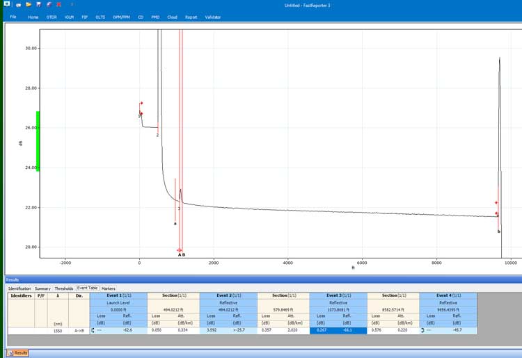
The sender wanted to know why there was a reflective event in the fiber -
had it been broken or spliced? That reflective event is a ghost, easily
recognized by the fact that the connection between the launch cable
(500 feet long) was high loss and highly reflective (it was a bare fiber
adapter) and the second reflection was another 500 feet away. The decay
from the connection to the launch cable was due to a bare fiber adapter
with ~4 dB loss and a lot of reflectance (-25.7 dB) overloading the
OTDR receiver.
There was nothing wrong with the fiber.
The second trace was for a longer fiber, still a cable on a reel before installation:
The question was why was there a "gainer" in the middle of the fiber.
The trace sent to FOA showed a noisy trace with a "gainer" at around
5500 feet. Again there seems to be no problem with the fiber, but the
OTDR setup caused the noisy trace and that "gainer" was because the
noise exceeded the threshold for events set in the OTDR. Redoing the
trace with a longer test pulse or longer integration time should reduce
to noise. In this case, just knowing the fiber was continuous with no
splices tells you a gainer (caused by the joint between two different
fibers) was not the cause of the event. And looking at the noise on the
fiber says the OTDR is either not properly set up or defective.
I
have 4 questions about OTDRs:
Q: What
is dynamic range I read many time but can’t understand yet,
whether it is a range of losses can be measured by OTDR for
example if an OTDR has 45 dB dynamic range, it can read the
losses of point up to 45 dB or what it means.
A: I do
not believe there is a standard definition of dynamic range, but
it is generally accepted to be the highest loss of the longest
cable where you can see the end of the cable. That usually means
using the longest test pulse and most averaging and
assuming the end of the cable has a significant reflection.
Q: What
is dead zone is it fixed in meters mean an OTDR cannot measure
up to initial 5, 10 or 20 meter
A: The dead zone is a function of the pulse width and
speed of the OTDR amplifier. For most OTDRs it’s about 2-3 times
the test pulse width.
Q: What
Type of OTDR settings are needed before launching a test
A: See FOA
Lecture 18: OTDR Setup or the section "Modifying OTDR
Setup Parameters For Best Test Results” in OTDR
testing. A: Basically you set up wavelength(s), test pulse
width (long enough to reach end of cable but short enough for
best resolution), index of refraction or group velocity (a
function of the fiber type and wavelength) and the number of
averages (enough to mitigate noise but not take too long)
Q: Reading a test with 1310nm and 1550nm - why values
different for a same length of fiber.
A: The attenuation of the fiber will be different at each
wavelength and the index of refraction which is different at
each wavelength causes a difference in length. The OTDR measures
length by measuring time and then multiplying that by the speed
of light in the fiber (which is the inverse of the index of
refraction.)
The FOA page "Frequently
Asked Questions About OTDRs" answers these questions and
more.
"Connector
Loss" or "Connection Loss"
Q: I have always counted the loss of a connector as .75
dB (568B-3) and 1.5 for a mated pair. Is that correct?
A: While the industry
always says "connector" loss, it is actually "connection" loss.
As we explain in the page on termination and splicing (http://www.thefoa.org/tech/ref/basic/term.html)
When we say "connector" loss, we really mean "connection" loss -
the loss of a mated pair of connectors, expressed in "dB." Thus,
testing connectors requires mating them to reference connectors
which must be high quality connectors themselves to not
adversely affect the measured loss when mated to an unknown
connector. This is an important point often not fully
explained. In order to measure the loss of the connectors
you must mate them to a similar, known good, connector. When a
connector being tested is mated to several different connectors,
it may have different losses, because those losses are dependent
on the reference connector it is mated to."
The TIA spec of 0.75dB is for a mated pair of connectors. If you
have been passing connectors tested @ 1.5dB loss....you may have
some very bad connectors in your cabling!
Optical
Loss: Are You Positive It’s Positive? A question we get often.
A recent
post on a company’s
blog and
article on the CI&M website discussed the topic of the
polarity (meaning “+” or “-“ numbers) of measurements of optical
loss, claiming loss was a positive number. The implication was
that some people failed fourth grade math and did not understand
positive and negative numbers. The claim is that insertion loss
is always a positive number.
Is that right? Well, it depends if you argue from the standpoint
of scientific convention or from the standpoint of one isolated
standard!
In
IEC (and TIA documents adopted from IEC documents, the
definition of attenuation in Sec. 3.1 is written to have
attenuation calculated based on Power(reference)/Power
(after attenuation). This definition leads to attenuation
being a positive number as it is normally displayed by an
OLTS or OTDR. However if one uses a fiber optic power
meter calibrated in dBm, the result will be a negative
number, since dBm is defined as Power(measured)/Power(1mw)
(see FOTP-95, Sec. 6.2). If dBm were defined in this manner,
power levels below 1mW would be positive numbers, not
negative as they are now, and power levels above 1mW would
be negative!
Well the real problem is that to understand this you need to
understand logarithms and that’s Algebra II*, way beyond fourth
grade addition and subtraction. You see dB is defined as a
logarithmic function:
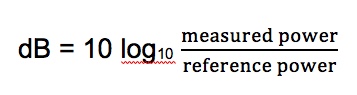
With logarithms, if the ratio of measured power to reference
power is greater than 1, e.g. measured power is more than
reference power, the log is positive. If the ratio of measured
power to reference power is less than 1, e.g. measured power is
more than reference power, the log is negative. If the ratio is
1, the log is 0.
Since the logarithm for optical power ratio is base 10 and then
multiplied by 10, each change of 10 in the ratio of the measured
and reference power becomes a change of 10dB. E.g. +10 dB is a
factor of 10 (10 times log10 10 which is 1), +20dB is a factor
of 100 (10 times log10 100 which is 2), +30dB a factor of
1000 (10 times log10 1000 which is 3)and so on. Negative
dB means division, so -10 dB means a factor of 1/10th (10
times log10 0.1 which is -1), -20dB a factor of 1/100th
(10 times log10 0.01 which is -2) and so on. 0 dB means the
measured power to reference power ratio is 1 – they are equal.
Let’s try a graphic explanation of this equation. Take a look at
this “semi-log” graph (logarithmic on the x axis and linear on
the y axis) of dBm vs optical power in the range commonly used
for fiber optics and calculated with our equation above.
Remember 0 dBm means all power is referenced to 1 milliwatt
optical power.
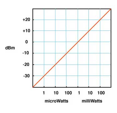
As you move to the right, power increases and the value in dBm
gets more positive – that would be gain. So from 1mw to 10mw, we
see a gain from 0dBm to +10dBm or 10dB, a positive change.
As you move to the left, to lower optical power, as would be
loss, the dBm value gets more negative. From 1mw to
100microwatts (that’s 1/10mw), we go from 0dBm to -10dBm, or
-10dB; that negative change indicating a loss of 10dB.
That shows gain is positive dB and loss is negative dB. Now
we’re getting to the fourth grade math.*
How about an example? Let’s say we decide to test a singlemode
cable plant. We start with a laser source and launch cable which
we measure our reference level for loss with a power meter to
have an output of 0dBm. That’s 1 milliwatt of power, about the
normal output of a fiber optic laser. After we attach the cable
plant to test and a receive cable to our power meter, we measure
3dB loss.
What power did we measure? The power must be lower, of course,
since we have loss, and 3dB is approximately a factor of 2, so
the power the meter measured is 1mw divided by 2 = 1/2milliwatt
or 0.5mw. Since our power meter is measuring in dBm, it will
read minus 3dBm (-3 dBm), since lower optical power is always
more negative. If it read +3dBm, the power measured would be 2mw
and that would be a gain from our reference (0dBm) which we know
is incorrect – passive cable plants are not fiber amplifiers.
Here is the graphical version of this loss test:
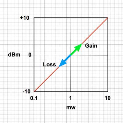
And then there is this short movie on the FOA
Guide page explaining dB showing how a power meter shows
loss when a cable is stressed to induce loss:
As the fiber is stressed, inducing loss, the power level goes
from -20.0 dBm to --22.3 dBm.That's a more negative number.
No question – loss means a more negative power reading in dB and
a negative number in dB indicates loss.**
But if you are a manufacturer of fiber optic test instruments
that offers optical power meters and sources to test loss, why
would this confuse you?
Perhaps we should blame accounting.
Suppose you have a company that has $1million in sales and
$900,000 in expenses. What’s the profit? It’s $1,000,000 -
$900,000 = $100,000. That’s a profit, right?
But suppose your company has $1million in sales and $1,100,000
in expenses. What’s the bottom line? It’s $1,000,000 -
$1,100,000 = - $100,000. Wait a minute, that is a negative
number – that’s not a profit, it’s a loss.
So in accounting, profits are positive numbers and losses are
negative numbers when we do the math, but when we talk about
loss, we don’t say we have a loss of “-$100,000,” we just have
we have a loss of $100,000. Then we’ll put that number in
parentheses when we publish our P&L like this ($100,000) and
hope it doesn’t get noticed by investors, but you know it will.
Loss and gain in fiber optic measurements are similar. If you
are using a separate source and power meter, loss will be a
negative number and gain will be a positive number. But because
of convention, we sometimes drop the signs when we report the
values because loss always means the optical power measurement
was negative and gain means the optical power measurement was
positive. But maybe that’s not what the convention has evolved
to.
Optical loss test sets (OLTS) aren’t designed to measure and
display optical power, just loss. The actual power measured is
lost in the algorithms used for calculating loss based on the
“0dB” reference power and the measured loss. Long ago, most OLTS
measured loss and displayed it as a negative number, but some
companies who got into the fiber optic test equipment business
from other test businesses arbitrarily decided to display loss
as a positive number, and today most OLTS do show loss as a
positive number. But when the instrument sees a gain, which it
can do if improperly used, it therefore displays a negative
number, which can be very confusing to a trained fiber tech who
understands fiber optic power and loss measurements.
OTDRs do the same thing. I looked at traces from a half-dozen
OTDRs and all showed loss as a positive number and gain as a
negative number. And yes, when you have a gainer in one
direction, they show it as a negative number. Telling them that
is wrong will fall on deaf ears, I’m afraid.
The same article/blog post goes on to discuss optical return
loss and reflectance, which has similar issues but they get it
more or less right, which is confusing. Why can they understand
that more negative numbers for reflectance means lower power in
the reflectance but claim the opposite for insertion loss?
The “less right” is that with most OTDRs reflectance of an event
and optical return loss (ORL) are not the same thing. ORL is the
summation of all reflectance events and fiber backscatter from
the entire length of fiber.
And, please, please stop saying “back reflection;” a reflection
always goes back toward the source so the term is redundant and
was dropped from fiber optics years ago.
*So the problem is not simply fourth grade math, it also
involves a bit of convention and tradition and marketing. And it
requires understanding logarithms that create the negative
number of loss. That’s more like Algebra II or 7th grade math,
and here is a good tutorial from Kahn Academy on that: https://www.khanacademy.org/math/algebra2/exponential-and-logarithmic-functions/introduction-to-logarithms/v/logarithms
And more basic, here is a tutorial on adding and subtracting
negative numbers https://www.khanacademy.org/math/cc-seventh-grade-math
** If you want to calculate this yourself, FOA
has a XLS spreadsheet you can download that will calculate
the equations for optical power for you.
The FOA has an explanation
of dB on our online Guide and a couple of graphics that
illustrate what happens with loss.
Note: In IEC (and TIA documents adopted
from IEC documents, the definition of attenuation in Sec. 3.1
is written to have attenuation calculated based on
Power(reference)/Power (after attenuation). This definition
leads to attenuation being a positive number as it is normally
displayed by an OLTS or OTDR. However if one uses a
fiber optic power meter calibrated in dBm, the result will be
a negative number, since dBm is defined as
Power(measured)/Power(1mw) (see FOTP-95, Sec. 6.2). If dBm
were defined in this manner, power levels below 1mW would be
positive numbers, not negative as they are now, and power
levels above 1mW would be negative!
Education/Learning
Using FOA Resources To Learn
Q: I've been working in this industry since
October 2018. Started as a Field Service Engineer
fielding aerial and underground. I have since become
a Project Engineer working with aerial OSP and ISP.
What is the catch? This is just an amazing platform
to continue with for me. It's been all about the
OJT, but this is just a great resource for me now
and the YouTube videos allow me to watch your videos
from today as well as 10 plus years ago.
How can I use the website to benefit me? Where
should I start? I just want to watch every YouTube
video before I focus on your website, but maybe I
want to do both, Suggestions?
A: FOA has three options to get information:
FOA
Guide is the FOA knowledgebase, ~1000 pages of
technical material generated by the FOA technical
advisors around the world. The link is to the Table
of Contents where you can find pages on just about
any topic in fiber optics from fiber to coherent
communications. Every year about 1/2 million users
download about 4 million pages!
Linked from the Guide above is the FOA YouTube
channel which you have found. It’s over 100 videos,
about 60 lectures on tech topics, where you can get
very familiar with my voice - I’m the lecturer. The
FOA videos are listed here:
https://foa.org/tech/ref/contents.html#YT
You can also go to the FOA channel on YouTube: go to
the FOA Channel “thefoainc"
Fiber
U is our free online learning site. We
started online learning at Fiber U in 1997. Today it
has over two dozen free online self-study courses
that lead to a Fiber U Certificate of Completion.
Courses include Basics of Fiber Optics with an
accompanying Basic Skills Lab, where many people
start, especially if they are aiming at FOA CFOT
certification, the primary certification from FOA.
We also have basic courses on premises cabling, OSP
construction and installation, splicing,
termination, testing, network design and about
a dozen that cover specific applications. The
FTTH course was developed when Verizon approached
FOA in 2005/6 to help with the rollout of FiOS -
training and recruiting installers.
FOA”s problem is we have too much “stuff”! It’s so
much it can be confusing on where to start. We
generally recommend going to Fiber U and picking
courses that are important to your work. Those
courses will lead you to the appropriate pages in
the FOA Guide and videos on YouTube.
But we are always here to help. Tell us what you are
interested in and we can point you to the right
places (often including websites of manufacturers of
products who also have immense amounts of
applications information.)
We’re
now working on a “Roadmap” to help people find their
way, but that will take time, there are a lot of
paths to connect!
Are
FOA Videos and Web Up To Date?
Q: Are the videos on
YouTube still relevant by today's standards are are they out of
date?
A: Excellent question. We’ve discussed this within the
FOA many times.
For example the live action videos on cable preparation,
termination, mechanical and fusion splicing and testing are
quite old by tech standards but the processes have not changed
in two decades. Preparing loose tube, armored or tight buffer
cables has not changed in over 20 years, nor has adhesive/polish
connector termination. Prepolished/splice connector and SOC
process are different and those processes have been updated.
Testing processes are the same with the main difference being
the automating of OTDR testing. Manufacturers have dumbed-down
OTDRs so well that it seems few techs know how they work or how
to read a trace, evidenced by the results of the FOA CFOT
Certification exam where questions on OTDRs are the most often
missed.
We just did a review of the copper installation for the Premises
cabling (CPCT Certification) and that has not really changed in
three decades - since the introduction of Cat 5 cable!
We review and update the technical pages in the FOA Guide all
the time. Look at the Table of Contents (FOA Guide-https://foa.org/tech/ref/contents.html)
and see how many pages have the NEW symbol, indicating updates
in the last couple of months.
Also FOA is adding YouTube videos (https://foa.org/tech/ref/contents.html#YT
) and Fiber U MiniCourses (https://fiberu.org) on many topics
regularly - monthly this year, covering new tech and the topics
we know are lesser-known or new to most techs.
And let us know if there are topics you think we should focus on
in the future.
Math
of Fiber Optics
Q: Do you by any
chance recommend any books as an introduction to understand the
mathematics of fiber optics? Fiber optics confuses me,
particularly how so much data can travel over light without
interfering with each other,
A: If you are interested in information theory, that’s
really covered by Claude Shannon at Bell Labs 70 years ago.
That’s actually pretty simple. Shannon proved that digital data
was best and how much data could be transmitted with a given
amount of bandwidth (Read
more). There are several levels of math associated with
fiber optics. The real theoretical basis is probably in dozens
of books but I like these:
Top Level: Gerd
Keiser
Middle Level: Jeff
Hecht.
If you are interested in non-math explanations, the FOA website
has that:
Fiber
Optic Datalinks
Bandwidth: https://foa.org/tech/ref/OSP/fiber.html#dispersion
Wavelength-Division
Multiplexing
For testing math (dB loss, metrology, etc.) these links or the FOA
book on Testing
Metrology
and Fiber Optics
The
Math of Insertion Loss Testing - Reference Methods
Have
An Old Cell Phonet? Use it to test for infrared light in fiber
optics. See the video on 
Yes!
The camera in your old cell phone is sensitive to infrared light
- lots more than your eye - and can detect light in an optical
fiber or from a transmitter. Chris Hillyer,CFOT/CFOS/I,
Master Instructor, Northern California Sound & Communication
JATC brought this to our attention.
If
you have an old cell phone, try it. Our experience is that older
cell phone cameras have better sensitivity at IR wavelengths
than newer phones, so you may want to toss that old flip phone
into the toolbox.
|